

5.7.1: Packet Tracer Skills Integration Challenge Activity
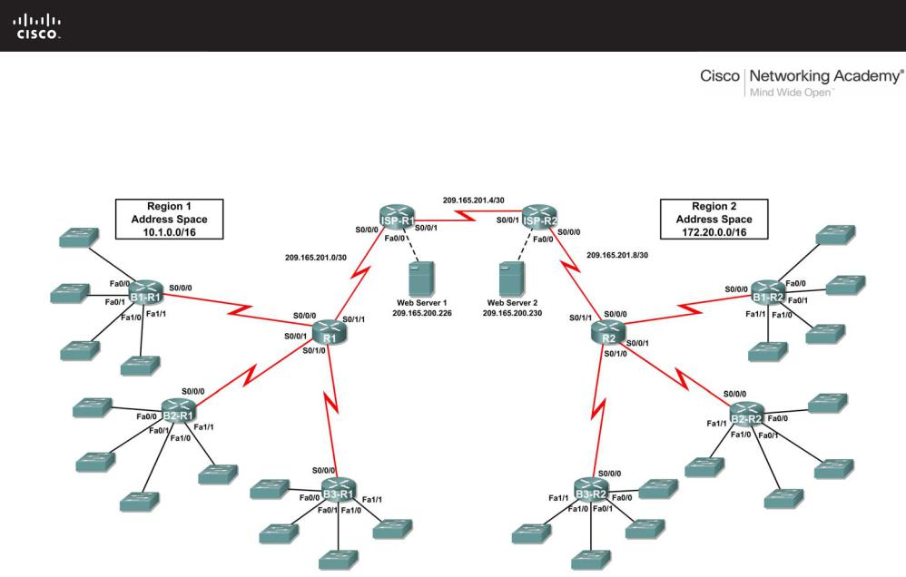
Topology Diagram
All contents are Copyright © 1992–2007 Cisco Systems, Inc. All rights reserved. This document is Cisco Public Information. |
Page 1 of 6 |

CCNA Exploration |
|
Routing Protocols and Concepts: RIP version 1 |
5.7.1: Packet Tracer Skills Integration challenge Activity |
Addressing Table for R1
|
Device |
|
Interface |
IP Address |
Subnet Mask |
|
|
|
|
|
|
|
|
|
S0/0/0 |
|
|
|
|
|
|
|
|
|
R1 |
|
S0/0/1 |
|
|
|
|
|
|
|
|
|
|
S0/1/0 |
|
|
|
|
|
|
|
|
|
|
|
|
|
|
|
|
|
|
S0/1/1 |
209.165.201.2 |
255.255.255.252 |
|
|
|
|
|
|
|
|
|
Fa0/0 |
|
|
|
|
|
|
|
|
|
|
|
Fa0/1 |
|
|
|
B1-R1 |
|
|
|
|
|
|
Fa1/0 |
|
|
|
|
|
|
|
|
|
|
|
|
Fa1/1 |
|
|
|
|
|
|
|
|
|
|
|
S0/0/0 |
|
|
|
|
|
|
|
|
|
|
|
Fa0/0 |
|
|
|
|
|
|
|
|
|
|
|
Fa0/1 |
|
|
|
B2-R1 |
|
|
|
|
|
|
Fa1/0 |
|
|
|
|
|
|
|
|
|
|
|
|
Fa1/1 |
|
|
|
|
|
|
|
|
|
|
|
S0/0/0 |
|
|
|
|
|
|
|
|
|
|
|
Fa0/0 |
|
|
|
|
|
|
|
|
|
|
|
Fa0/1 |
|
|
|
B3-R1 |
|
|
|
|
|
|
Fa1/0 |
|
|
|
|
|
|
|
|
|
|
|
|
Fa1/1 |
|
|
|
|
|
|
|
|
|
|
|
S0/0/0 |
|
|
|
|
|
|
|
|
|
|
|
S0/0/0 |
209.165.201.1 |
255.255.255.252 |
|
ISP-R1 |
|
|
|
|
|
|
S0/0/1 |
209.165.201.5 |
255.255.255.252 |
|
|
|
|
|
|
|
|
|
|
Fa0/0 |
209.165.200.225 |
255.255.255.252 |
|
|
|
|
|
|
|
Web Server 1 |
|
NIC |
209.165.200.226 |
255.255.255.252 |
|
|
|
|
|
|
All contents are Copyright © 1992–2007 Cisco Systems, Inc. All rights reserved. This document is Cisco Public Information. |
Page 2 of 6 |

CCNA Exploration |
|
Routing Protocols and Concepts: RIP version 1 |
5.7.1: Packet Tracer Skills Integration challenge Activity |
Addressing Table for R2
|
Device |
|
Interface |
IP Address |
Subnet Mask |
|
|
|
|
|
|
|
|
|
S0/0/0 |
|
|
|
|
|
|
|
|
|
R2 |
|
S0/0/1 |
|
|
|
|
|
|
|
|
|
|
S0/1/0 |
|
|
|
|
|
|
|
|
|
|
|
|
|
|
|
|
|
|
S0/1/1 |
209.165.201.10 |
255.255.255.252 |
|
|
|
|
|
|
|
|
|
Fa0/0 |
|
|
|
|
|
|
|
|
|
|
|
Fa0/1 |
|
|
|
B1-R2 |
|
|
|
|
|
|
Fa1/0 |
|
|
|
|
|
|
|
|
|
|
|
|
Fa1/1 |
|
|
|
|
|
|
|
|
|
|
|
S0/0/0 |
|
|
|
|
|
|
|
|
|
|
|
Fa0/0 |
|
|
|
|
|
|
|
|
|
|
|
Fa0/1 |
|
|
|
B2-R2 |
|
|
|
|
|
|
Fa1/0 |
|
|
|
|
|
|
|
|
|
|
|
|
Fa1/1 |
|
|
|
|
|
|
|
|
|
|
|
S0/0/0 |
|
|
|
|
|
|
|
|
|
|
|
Fa0/0 |
|
|
|
|
|
|
|
|
|
|
|
Fa0/1 |
|
|
|
B3-R2 |
|
|
|
|
|
|
Fa1/0 |
|
|
|
|
|
|
|
|
|
|
|
|
Fa1/1 |
|
|
|
|
|
|
|
|
|
|
|
S0/0/0 |
|
|
|
|
|
|
|
|
|
|
|
S0/0/0 |
209.165.201.6 |
255.255.255.252 |
|
ISP-R2 |
|
|
|
|
|
|
S0/0/1 |
209.165.201.9 |
255.255.255.252 |
|
|
|
|
|
|
|
|
|
|
Fa0/0 |
209.165.200.229 |
255.255.255.252 |
|
|
|
|
|
|
|
Web Server 2 |
|
NIC |
209.165.200.230 |
255.255.255.252 |
|
|
|
|
|
|
Objectives
•Design and document an addressing scheme based on requirements.
•Apply a basic configuration to the devices.
•Configure static routing between ISP routers.
•Configure RIPv1 routing in Region 1 and Region 2
•Disable RIP updates on appropriate interfaces
•Configure default routes and redistribute through RIP
•Verify full connectivity between all devices in the topology.
All contents are Copyright © 1992–2007 Cisco Systems, Inc. All rights reserved. This document is Cisco Public Information.

CCNA Exploration |
|
Routing Protocols and Concepts: RIP version 1 |
5.7.1: Packet Tracer Skills Integration challenge Activity |
Task 1: Design and document an addressing scheme.
Step 1: Design an addressing scheme.
Using the topology and the following requirements, design an addressing scheme:
•The WAN links between R1 and R2 and their respective ISP routers are already configured. Also, the links between the ISPs and the Web Servers are already configured.
•Since RIPv1 is a classful routing protocol, you cannot implement Variable Length Subnet Masks (VLSM). Subnet each region’s address space using the following guidelines:
The largest subnet in Region 1’s address space is 1,000 hosts. What is the subnet mask you should use for the 10.1.0.0/16 address space? __________________________
The largest subnet in Region 2’s address space is 500 hosts. What is the subnet mask you should use for the 172.20.0.0/16 address space? __________________________
•For the LANs in Region 1, assign subnet 0 to the LAN attached to FastEthernet 0/0 on B1-R1. Continue to assign LANs in sequence. Subnet 1 is assigned to the LAN attached to FastEthernet 0/1 on B1-R1; Subnet 2 to FastEthernet 1/0; Subnet 3 to FastEthernet 1/1 and so on.
•For the WANs in Region 1, assign the last subnet to the link between R1 and B3-R1, the second to last subnet to the link between R1 and B2-R1 and the third to the last subnet to link between R1 and B1-R1.
•Record the Region 1 subnet assignments in the following table:
|
Router |
|
|
Subnet |
|
|
Subnet Address |
|
|
|
|
|
|||||
|
|
|
Number |
|
|
|
||
|
|
|
|
|
|
|
|
|
|
|
|
|
|
|
|
|
|
|
B1-R1 Fa0/0 |
0 |
|
|
|
|
||
|
|
|
|
|
|
|
||
|
B1-R1 Fa0/1 |
1 |
|
|
|
|
||
|
|
|
|
|
|
|
||
|
B1-R1 Fa1/0 |
2 |
|
|
|
|
||
|
|
|
|
|
|
|
||
|
B1-R1 Fa1/1 |
3 |
|
|
|
|
||
|
|
|
|
|
|
|
||
|
B2-R1 Fa0/0 |
4 |
|
|
|
|
||
|
|
|
|
|
|
|
||
|
B2-R1 Fa0/1 |
5 |
|
|
|
|
||
|
|
|
|
|
|
|
||
|
B2-R1 Fa1/0 |
6 |
|
|
|
|
||
|
|
|
|
|
|
|
||
|
B2-R1 Fa1/1 |
7 |
|
|
|
|
||
|
|
|
|
|
|
|
||
|
B3-R1 Fa0/0 |
8 |
|
|
|
|
||
|
|
|
|
|
|
|
||
|
B3-R1 Fa0/1 |
9 |
|
|
|
|
||
|
|
|
|
|
|
|
||
|
B3-R1 Fa1/0 |
10 |
|
|
|
|
||
|
|
|
|
|
|
|
||
|
B3-R1 Fa1/1 |
11 |
|
|
|
|
||
|
|
|
|
|
|
|
||
|
B1-R1 <--> R1 |
|
3rd to Last |
|
|
|
||
|
B2-R1 <--> R1 |
|
2nd to Last |
|
|
|
||
|
B3-R1 <--> R1 |
|
Last |
|
|
|
||
|
|
|
|
|
|
|
|
|
All contents are Copyright © 1992–2007 Cisco Systems, Inc. All rights reserved. This document is Cisco Public Information.

CCNA Exploration |
|
Routing Protocols and Concepts: RIP version 1 |
5.7.1: Packet Tracer Skills Integration challenge Activity |
•For the LANs in Region 2, following the same format for assigning subnets that you used for Region 1: Subnet 0 to the Fa0/0 interface on B1-R2; Subnet 1 to Fa0/1, and so on.
•For the WANs in Region 2, assign the last subnet to the link between R2 and B3-R2, the second to last subnet to the link between R2 and B2-R2 and the third to the last subnet to link between R2 and B1-R2.
•Record the Region 2 subnet assignments in the following table:
|
Router |
|
|
Subnet |
|
|
Subnet Address |
|
|
|
|
|
|||||
|
|
|
Number |
|
|
|
||
|
|
|
|
|
|
|
|
|
|
|
|
|
|
|
|
|
|
|
B1-R2 Fa0/0 |
0 |
|
|
|
|
||
|
|
|
|
|
|
|
||
|
B1-R2 Fa0/1 |
1 |
|
|
|
|
||
|
|
|
|
|
|
|
||
|
B1-R2 Fa1/0 |
2 |
|
|
|
|
||
|
|
|
|
|
|
|
||
|
B1-R2 Fa1/1 |
3 |
|
|
|
|
||
|
|
|
|
|
|
|
||
|
B2-R2 Fa0/0 |
4 |
|
|
|
|
||
|
|
|
|
|
|
|
||
|
B2-R2 Fa0/1 |
5 |
|
|
|
|
||
|
|
|
|
|
|
|
||
|
B2-R2 Fa1/0 |
6 |
|
|
|
|
||
|
|
|
|
|
|
|
||
|
B2-R2 Fa1/1 |
7 |
|
|
|
|
||
|
|
|
|
|
|
|
||
|
B3-R2 Fa0/0 |
8 |
|
|
|
|
||
|
|
|
|
|
|
|
||
|
B3-R2 Fa0/1 |
9 |
|
|
|
|
||
|
|
|
|
|
|
|
||
|
B3-R2 Fa1/0 |
10 |
|
|
|
|
||
|
|
|
|
|
|
|
||
|
B3-R2 Fa1/1 |
11 |
|
|
|
|
||
|
|
|
|
|
|
|
||
|
B1-R2 <--> R2 |
|
3rd to Last |
|
|
|
||
|
B2-R2 <--> R2 |
|
2nd to Last |
|
|
|
||
|
B3-R2 <--> R2 |
|
Last |
|
|
|
||
|
|
|
|
|
|
|
|
|
Step 2: Document the addressing scheme.
•Optional: On the topology, label each subnet. To save space, use only the last two octets since only these octets change.
•Use the table provided in the printed instructions to document the IP addresses and subnet masks. Assign the first IP address to the router interface.
•For the WAN links, assign the first IP address to R1 and R2 for links to each router’s respective B1, B2, and B3 routers.
Task 3: Apply a basic configuration.
Using your documentation, configure the routers with basic configurations including addressing. Use cisco as the line passwords and class as the secret password. Use 64000 as the clock rate.
Task 4: Configure static routing between ISP routers.
Each ISP router already has two static routes to the other ISP router’s directly connected WANs. Implement static routing on each ISP router to insure connectivity between the two regions.
All contents are Copyright © 1992–2007 Cisco Systems, Inc. All rights reserved. This document is Cisco Public Information.

CCNA Exploration |
|
Routing Protocols and Concepts: RIP version 1 |
5.7.1: Packet Tracer Skills Integration challenge Activity |
Task 5: Configure RIPv1 routing in Region 1 and Region 2.
Configure RIP routing on all regional routers. Remember, the ISP routers are only using static routing.
Task 6: Disable RIP updates on appropriate interfaces.
RIP updates do not need to be sent out all the router interfaces. Disable RIP updates on appropriate interfaces.
Task 7: Configure default routes and redistribute through RIP.
Determine which routers need a default route. Then configure that router to redistribute the default route to other routers in the region.
Task 8: Verify full connectivity between all devices in the topology.
Step 1: Test connectivity.
•You should now have end-to-end connectivity. Use ping to test connectivity across the network. Each router should be able to ping all other router interfaces and both Web Servers.
•Troubleshoot until pings are successful.
Step 2: Examine the configuration.
Use verification commands to make sure your configurations are complete.
All contents are Copyright © 1992–2007 Cisco Systems, Inc. All rights reserved. This document is Cisco Public Information.