
- •Contents
- •Symbols and Abbreviations
- •Symbols
- •Greek Symbols
- •Subscripts
- •Abbreviations
- •Preface
- •Road Map of the Book
- •The Arrangement
- •Suggested Route for the Coursework
- •First Semester
- •Second Semester
- •Suggestions for the Class
- •Use of Semi-empirical Relations
- •1 Introduction
- •1.1 Overview
- •1.1.1 What Is to Be Learned?
- •1.1.2 Coursework Content
- •1.2 Brief Historical Background
- •1.3 Current Aircraft Design Status
- •1.3.1 Forces and Drivers
- •1.3.2 Current Civil Aircraft Design Trends
- •1.3.3 Current Military Aircraft Design Trends
- •1.4 Future Trends
- •1.4.1 Civil Aircraft Design: Future Trends
- •1.4.2 Military Aircraft Design: Future Trends
- •1.5 Learning Process
- •1.6 Units and Dimensions
- •1.7 Cost Implications
- •2 Methodology to Aircraft Design, Market Survey, and Airworthiness
- •2.1 Overview
- •2.1.1 What Is to Be Learned?
- •2.1.2 Coursework Content
- •2.2 Introduction
- •2.3 Typical Design Process
- •2.3.1 Four Phases of Aircraft Design
- •2.3.2 Typical Resources Deployment
- •2.3.3 Typical Cost Frame
- •2.3.4 Typical Time Frame
- •2.4 Typical Task Breakdown in Each Phase
- •Phase 1: Conceptual Study Phase (Feasibility Study)
- •Phase 3: Detailed Design Phase (Full-Scale Product Development)
- •2.4.1 Functional Tasks during the Conceptual Study (Phase 1: Civil Aircraft)
- •2.4.2 Project Activities for Small Aircraft Design
- •Phase 1: Conceptual Design (6 Months)
- •Phase 3: Detailed Design (Product Development) (12 Months)
- •2.5 Aircraft Familiarization
- •Fuselage Group
- •Wing Group
- •Empennage Group
- •Nacelle Group
- •Undercarriage Group
- •2.6 Market Survey
- •2.7 Civil Aircraft Market
- •2.8 Military Market
- •2.9 Comparison between Civil and Military Aircraft Design Requirements
- •2.10 Airworthiness Requirements
- •2.11 Coursework Procedures
- •3 Aerodynamic Considerations
- •3.1 Overview
- •3.1.1 What Is to Be Learned?
- •3.1.2 Coursework Content
- •3.2 Introduction
- •3.3 Atmosphere
- •3.4 Fundamental Equations
- •3.5.1 Flow Past Aerofoil
- •3.6 Aircraft Motion and Forces
- •3.6.1 Motion
- •3.6.2 Forces
- •3.7 Aerofoil
- •3.7.1 Groupings of Aerofoils and Their Properties
- •NACA Four-Digit Aerofoil
- •NACA Five-Digit Aerofoil
- •NACA Six-Digit Aerofoil
- •Other Types of Aerofoils
- •3.9 Generation of Lift
- •3.10 Types of Stall
- •3.10.1 Gradual Stall
- •3.10.2 Abrupt Stall
- •3.11 Comparison of Three NACA Aerofoils
- •3.12 High-Lift Devices
- •3.13 Transonic Effects – Area Rule
- •3.14 Wing Aerodynamics
- •3.14.1 Induced Drag and Total Aircraft Drag
- •3.15 Aspect Ratio Correction of 2D Aerofoil Characteristics for 3D Finite Wing
- •3.16.1 Planform Area, SW
- •3.16.2 Wing Aspect Ratio
- •3.16.4 Wing Root (Croot) and Tip (Ctip) Chord
- •3.16.6 Wing Twist
- •3.17 Mean Aerodynamic Chord
- •3.18 Compressibility Effect: Wing Sweep
- •3.19 Wing Stall Pattern and Wing Twist
- •3.20.1 The Square-Cube Law
- •3.20.2 Aircraft Wetted Area (AW) versus Wing Planform Area (Sw)
- •3.20.3 Additional Vortex Lift
- •3.20.4 Additional Surfaces on Wing
- •3.21 Finalizing Wing Design Parameters
- •3.22 Empennage
- •3.22.1 H-Tail
- •3.22.2 V-Tail
- •3.23 Fuselage
- •3.23.2 Fuselage Length, Lfus
- •3.23.3 Fineness Ratio, FR
- •3.23.4 Fuselage Upsweep Angle
- •3.23.5 Fuselage Closure Angle
- •3.23.6 Front Fuselage Closure Length, Lf
- •3.23.7 Aft Fuselage Closure Length, La
- •3.23.8 Midfuselage Constant Cross-Section Length, Lm
- •3.23.9 Fuselage Height, H
- •3.23.10 Fuselage Width, W
- •3.23.11 Average Diameter, Dave
- •3.23.12 Cabin Height, Hcab
- •3.23.13 Cabin Width, Wcab
- •3.24 Undercarriage
- •3.25 Nacelle and Intake
- •3.26 Speed Brakes and Dive Brakes
- •4.1 Overview
- •4.1.1 What Is to Be Learned?
- •4.1.2 Coursework Content
- •4.2 Introduction
- •4.3 Aircraft Evolution
- •4.4 Civil Aircraft Mission (Payload-Range)
- •4.5 Civil Subsonic Jet Aircraft Statistics (Sizing Parameters and Regression Analysis)
- •4.5.1 Maximum Takeoff Mass versus Number of Passengers
- •4.5.2 Maximum Takeoff Mass versus Operational Empty Mass
- •4.5.3 Maximum Takeoff Mass versus Fuel Load
- •4.5.4 Maximum Takeoff Mass versus Wing Area
- •4.5.5 Maximum Takeoff Mass versus Engine Power
- •4.5.6 Empennage Area versus Wing Area
- •4.5.7 Wing Loading versus Aircraft Span
- •4.6 Civil Aircraft Component Geometries
- •4.7 Fuselage Group
- •4.7.1 Fuselage Width
- •4.7.2 Fuselage Length
- •4.7.3 Front (Nose Cone) and Aft-End Closure
- •4.7.4 Flight Crew (Flight Deck) Compartment Layout
- •4.7.5 Cabin Crew and Passenger Facilities
- •4.7.6 Seat Arrangement, Pitch, and Posture (95th Percentile) Facilities
- •4.7.7 Passenger Facilities
- •4.7.8 Cargo Container Sizes
- •4.7.9 Doors – Emergency Exits
- •4.8 Wing Group
- •4.9 Empennage Group (Civil Aircraft)
- •4.10 Nacelle Group
- •4.11 Summary of Civil Aircraft Design Choices
- •4.13 Military Aircraft Mission
- •4.14.1 Military Aircraft Maximum Take-off Mass (MTOM) versus Payload
- •4.14.2 Military MTOM versus OEM
- •4.14.3 Military MTOM versus Fuel Load Mf
- •4.14.4 MTOM versus Wing Area (Military)
- •4.14.5 MTOM versus Engine Thrust (Military)
- •4.14.6 Empennage Area versus Wing Area (Military)
- •4.14.7 Aircraft Wetted Area versus Wing Area (Military)
- •4.15 Military Aircraft Component Geometries
- •4.16 Fuselage Group (Military)
- •4.17 Wing Group (Military)
- •4.17.1 Generic Wing Planform Shapes
- •4.18 Empennage Group (Military)
- •4.19 Intake/Nacelle Group (Military)
- •4.20 Undercarriage Group
- •4.21 Miscellaneous Comments
- •4.22 Summary of Military Aircraft Design Choices
- •5 Aircraft Load
- •5.1 Overview
- •5.1.1 What Is to Be Learned?
- •5.1.2 Coursework Content
- •5.2 Introduction
- •5.2.1 Buffet
- •5.2.2 Flutter
- •5.3 Flight Maneuvers
- •5.3.1 Pitch Plane (X-Z) Maneuver (Elevator/Canard-Induced)
- •5.3.2 Roll Plane (Y-Z) Maneuver (Aileron-Induced)
- •5.3.3 Yaw Plane (Z-X) Maneuver (Rudder-Induced)
- •5.4 Aircraft Loads
- •5.4.1 On the Ground
- •5.4.2 In Flight
- •5.5.1 Load Factor, n
- •5.6 Limits – Load and Speeds
- •5.6.1 Maximum Limit of Load Factor
- •5.6.2 Speed Limits
- •5.7 V-n Diagram
- •5.7.1 Low-Speed Limit
- •5.7.2 High-Speed Limit
- •5.7.3 Extreme Points of a V-n Diagram
- •Positive Loads
- •Negative Loads
- •5.8 Gust Envelope
- •6.1 Overview
- •6.1.1 What Is to Be Learned?
- •6.1.2 Coursework Content
- •6.2 Introduction
- •Closure of the Fuselage
- •6.4 Civil Aircraft Fuselage: Typical Shaping and Layout
- •6.4.1 Narrow-Body, Single-Aisle Aircraft
- •6.4.2 Wide-Body, Double-Aisle Aircraft
- •6.4.3 Worked-Out Example: Civil Aircraft Fuselage Layout
- •6.5.1 Aerofoil Selection
- •6.5.2 Wing Design
- •Planform Shape
- •Wing Reference Area
- •Wing Sweep
- •Wing Twist
- •Wing Dihedral/Anhedral
- •6.5.3 Wing-Mounted Control-Surface Layout
- •6.5.4 Positioning of the Wing Relative to the Fuselage
- •6.6.1 Horizontal Tail
- •6.6.2 Vertical Tail
- •6.8 Undercarriage Positioning
- •6.10 Miscellaneous Considerations in Civil Aircraft
- •6.12.1 Use of Statistics in the Class of Military Trainer Aircraft
- •6.12.3 Miscellaneous Considerations – Military Design
- •6.13 Variant CAS Design
- •6.13.1 Summary of the Worked-Out Military Aircraft Preliminary Details
- •7 Undercarriage
- •7.1 Overview
- •7.1.1 What Is to Be Learned?
- •7.1.2 Coursework Content
- •7.2 Introduction
- •7.3 Types of Undercarriage
- •7.5 Undercarriage Retraction and Stowage
- •7.5.1 Stowage Space Clearances
- •7.6 Undercarriage Design Drivers and Considerations
- •7.7 Turning of an Aircraft
- •7.8 Wheels
- •7.9 Loads on Wheels and Shock Absorbers
- •7.9.1 Load on Wheels
- •7.9.2 Energy Absorbed
- •7.11 Tires
- •7.13 Undercarriage Layout Methodology
- •7.14 Worked-Out Examples
- •7.14.1 Civil Aircraft: Bizjet
- •Baseline Aircraft with 10 Passengers at a 33-Inch Pitch
- •Shrunk Aircraft (Smallest in the Family Variant) with 6 Passengers at a 33-Inch Pitch
- •7.14.2 Military Aircraft: AJT
- •7.15 Miscellaneous Considerations
- •7.16 Undercarriage and Tire Data
- •8 Aircraft Weight and Center of Gravity Estimation
- •8.1 Overview
- •8.1.1 What Is to Be Learned?
- •8.1.2 Coursework Content
- •8.2 Introduction
- •8.3 The Weight Drivers
- •8.4 Aircraft Mass (Weight) Breakdown
- •8.5 Desirable CG Position
- •8.6 Aircraft Component Groups
- •8.6.1 Civil Aircraft
- •8.6.2 Military Aircraft (Combat Category)
- •8.7 Aircraft Component Mass Estimation
- •8.8 Rapid Mass Estimation Method: Civil Aircraft
- •8.9 Graphical Method for Predicting Aircraft Component Weight: Civil Aircraft
- •8.10 Semi-empirical Equation Method (Statistical)
- •8.10.1 Fuselage Group – Civil Aircraft
- •8.10.2 Wing Group – Civil Aircraft
- •8.10.3 Empennage Group – Civil Aircraft
- •8.10.4 Nacelle Group – Civil Aircraft
- •Jet Type (Includes Pylon Mass)
- •Turboprop Type
- •Piston-Engine Nacelle
- •8.10.5 Undercarriage Group – Civil Aircraft
- •Tricycle Type (Retractable) – Fuselage-Mounted (Nose and Main Gear Estimated Together)
- •8.10.6 Miscellaneous Group – Civil Aircraft
- •8.10.7 Power Plant Group – Civil Aircraft
- •Turbofans
- •Turboprops
- •Piston Engines
- •8.10.8 Systems Group – Civil Aircraft
- •8.10.9 Furnishing Group – Civil Aircraft
- •8.10.10 Contingency and Miscellaneous – Civil Aircraft
- •8.10.11 Crew – Civil Aircraft
- •8.10.12 Payload – Civil Aircraft
- •8.10.13 Fuel – Civil Aircraft
- •8.11 Worked-Out Example – Civil Aircraft
- •8.11.1 Fuselage Group Mass
- •8.11.2 Wing Group Mass
- •8.11.3 Empennage Group Mass
- •8.11.4 Nacelle Group Mass
- •8.11.5 Undercarriage Group Mass
- •8.11.6 Miscellaneous Group Mass
- •8.11.7 Power Plant Group Mass
- •8.11.8 Systems Group Mass
- •8.11.9 Furnishing Group Mass
- •8.11.10 Contingency Group Mass
- •8.11.11 Crew Mass
- •8.11.12 Payload Mass
- •8.11.13 Fuel Mass
- •8.11.14 Weight Summary
- •Variant Aircraft in the Family
- •8.12 Center of Gravity Determination
- •8.12.1 Bizjet Aircraft CG Location Example
- •8.12.2 First Iteration to Fine Tune CG Position Relative to Aircraft and Components
- •8.13 Rapid Mass Estimation Method – Military Aircraft
- •8.14 Graphical Method to Predict Aircraft Component Weight – Military Aircraft
- •8.15 Semi-empirical Equation Methods (Statistical) – Military Aircraft
- •8.15.1 Military Aircraft Fuselage Group (SI System)
- •8.15.2 Military Aircraft Wing Mass (SI System)
- •8.15.3 Military Aircraft Empennage
- •8.15.4 Nacelle Mass Example – Military Aircraft
- •8.15.5 Power Plant Group Mass Example – Military Aircraft
- •8.15.6 Undercarriage Mass Example – Military Aircraft
- •8.15.7 System Mass – Military Aircraft
- •8.15.8 Aircraft Furnishing – Military Aircraft
- •8.15.11 Crew Mass
- •8.16.1 AJT Fuselage Example (Based on CAS Variant)
- •8.16.2 AJT Wing Example (Based on CAS Variant)
- •8.16.3 AJT Empennage Example (Based on CAS Variant)
- •8.16.4 AJT Nacelle Mass Example (Based on CAS Variant)
- •8.16.5 AJT Power Plant Group Mass Example (Based on AJT Variant)
- •8.16.6 AJT Undercarriage Mass Example (Based on CAS Variant)
- •8.16.7 AJT Systems Group Mass Example (Based on AJT Variant)
- •8.16.8 AJT Furnishing Group Mass Example (Based on AJT Variant)
- •8.16.9 AJT Contingency Group Mass Example
- •8.16.10 AJT Crew Mass Example
- •8.16.13 Weights Summary – Military Aircraft
- •8.17 CG Position Determination – Military Aircraft
- •8.17.1 Classroom Worked-Out Military AJT CG Location Example
- •8.17.2 First Iteration to Fine Tune CG Position and Components Masses
- •9 Aircraft Drag
- •9.1 Overview
- •9.1.1 What Is to Be Learned?
- •9.1.2 Coursework Content
- •9.2 Introduction
- •9.4 Aircraft Drag Breakdown (Subsonic)
- •9.5 Aircraft Drag Formulation
- •9.6 Aircraft Drag Estimation Methodology (Subsonic)
- •9.7 Minimum Parasite Drag Estimation Methodology
- •9.7.2 Computation of Wetted Areas
- •Lifting Surfaces
- •Fuselage
- •Nacelle
- •9.7.3 Stepwise Approach to Compute Minimum Parasite Drag
- •9.8 Semi-empirical Relations to Estimate Aircraft Component Parasite Drag
- •9.8.1 Fuselage
- •9.8.2 Wing, Empennage, Pylons, and Winglets
- •9.8.3 Nacelle Drag
- •Intake Drag
- •Base Drag
- •Boat-Tail Drag
- •9.8.4 Excrescence Drag
- •9.8.5 Miscellaneous Parasite Drags
- •Air-Conditioning Drag
- •Trim Drag
- •Aerials
- •9.9 Notes on Excrescence Drag Resulting from Surface Imperfections
- •9.10 Minimum Parasite Drag
- •9.12 Subsonic Wave Drag
- •9.13 Total Aircraft Drag
- •9.14 Low-Speed Aircraft Drag at Takeoff and Landing
- •9.14.1 High-Lift Device Drag
- •9.14.2 Dive Brakes and Spoilers Drag
- •9.14.3 Undercarriage Drag
- •9.14.4 One-Engine Inoperative Drag
- •9.15 Propeller-Driven Aircraft Drag
- •9.16 Military Aircraft Drag
- •9.17 Supersonic Drag
- •9.18 Coursework Example: Civil Bizjet Aircraft
- •9.18.1 Geometric and Performance Data
- •Fuselage (see Figure 9.13)
- •Wing (see Figure 9.13)
- •Empennage (see Figure 9.13)
- •Nacelle (see Figure 9.13)
- •9.18.2 Computation of Wetted Areas, Re, and Basic CF
- •Fuselage
- •Wing
- •Empennage (same procedure as for the wing)
- •Nacelle
- •Pylon
- •9.18.3 Computation of 3D and Other Effects to Estimate Component
- •Fuselage
- •Wing
- •Empennage
- •Nacelle
- •Pylon
- •9.18.4 Summary of Parasite Drag
- •9.18.5 CDp Estimation
- •9.18.6 Induced Drag
- •9.18.7 Total Aircraft Drag at LRC
- •9.19 Coursework Example: Subsonic Military Aircraft
- •9.19.1 Geometric and Performance Data of a Vigilante RA-C5 Aircraft
- •Fuselage
- •Wing
- •Empennage
- •9.19.2 Computation of Wetted Areas, Re, and Basic CF
- •Fuselage
- •Wing
- •Empennage (same procedure as for the wing)
- •9.19.3 Computation of 3D and Other Effects to Estimate Component CDpmin
- •Fuselage
- •Wing
- •Empennage
- •9.19.4 Summary of Parasite Drag
- •9.19.5 CDp Estimation
- •9.19.6 Induced Drag
- •9.19.7 Supersonic Drag Estimation
- •9.19.8 Total Aircraft Drag
- •9.20 Concluding Remarks
- •10 Aircraft Power Plant and Integration
- •10.1 Overview
- •10.1.1 What Is to Be Learned?
- •10.1.2 Coursework Content
- •10.2 Background
- •10.4 Introduction: Air-Breathing Aircraft Engine Types
- •10.4.1 Simple Straight-Through Turbojet
- •10.4.2 Turbofan: Bypass Engine
- •10.4.3 Afterburner Engine
- •10.4.4 Turboprop Engine
- •10.4.5 Piston Engine
- •10.6 Formulation and Theory: Isentropic Case
- •10.6.1 Simple Straight-Through Turbojet Engine: Formulation
- •10.6.2 Bypass Turbofan Engine: Formulation
- •10.6.3 Afterburner Engine: Formulation
- •10.6.4 Turboprop Engine: Formulation
- •Summary
- •10.7 Engine Integration with an Aircraft: Installation Effects
- •10.7.1 Subsonic Civil Aircraft Nacelle and Engine Installation
- •10.7.2 Turboprop Integration to Aircraft
- •10.7.3 Combat Aircraft Engine Installation
- •10.8 Intake and Nozzle Design
- •10.8.1 Civil Aircraft Intake Design: Inlet Sizing
- •10.8.2 Military Aircraft Intake Design
- •10.9 Exhaust Nozzle and Thrust Reverser
- •10.9.1 Civil Aircraft Thrust Reverser Application
- •10.9.2 Civil Aircraft Exhaust Nozzles
- •10.9.3 Coursework Example of Civil Aircraft Nacelle Design
- •Intake Geometry (see Section 10.8.1)
- •Lip Section (Crown Cut)
- •Lip Section (Keel Cut)
- •Nozzle Geometry
- •10.9.4 Military Aircraft Thrust Reverser Application and Exhaust Nozzles
- •10.10 Propeller
- •10.10.2 Propeller Theory
- •Momentum Theory: Actuator Disc
- •Blade-Element Theory
- •10.10.3 Propeller Performance: Practical Engineering Applications
- •Static Performance (see Figures 10.34 and 10.36)
- •In-Flight Performance (see Figures 10.35 and 10.37)
- •10.10.5 Propeller Performance at STD Day: Worked-Out Example
- •10.11 Engine-Performance Data
- •Takeoff Rating
- •Maximum Continuous Rating
- •Maximum Climb Rating
- •Maximum Cruise Rating
- •Idle Rating
- •10.11.1 Piston Engine
- •10.11.2 Turboprop Engine (Up to 100 Passengers Class)
- •Takeoff Rating
- •Maximum Climb Rating
- •Maximum Cruise Rating
- •10.11.3 Turbofan Engine: Civil Aircraft
- •Turbofans with a BPR Around 4 (Smaller Engines; e.g., Bizjets)
- •Turbofans with a BPR around 5 or 7 (Larger Engines; e.g., RJs and Larger)
- •10.11.4 Turbofan Engine – Military Aircraft
- •11 Aircraft Sizing, Engine Matching, and Variant Derivative
- •11.1 Overview
- •11.1.1 What Is to Be Learned?
- •11.1.2 Coursework Content
- •11.2 Introduction
- •11.3 Theory
- •11.3.1 Sizing for Takeoff Field Length
- •Civil Aircraft Design: Takeoff
- •Military Aircraft Design: Takeoff
- •11.3.2 Sizing for the Initial Rate of Climb
- •11.3.3 Sizing to Meet Initial Cruise
- •11.3.4 Sizing for Landing Distance
- •11.4 Coursework Exercises: Civil Aircraft Design (Bizjet)
- •11.4.1 Takeoff
- •11.4.2 Initial Climb
- •11.4.3 Cruise
- •11.4.4 Landing
- •11.5 Coursework Exercises: Military Aircraft Design (AJT)
- •11.5.1 Takeoff – Military Aircraft
- •11.5.2 Initial Climb – Military Aircraft
- •11.5.3 Cruise – Military Aircraft
- •11.5.4 Landing – Military Aircraft
- •11.6 Sizing Analysis: Civil Aircraft (Bizjet)
- •11.6.1 Variants in the Family of Aircraft Design
- •11.6.2 Example: Civil Aircraft
- •11.7 Sizing Analysis: Military Aircraft
- •11.7.1 Single-Seat Variant in the Family of Aircraft Design
- •11.8 Sensitivity Study
- •11.9 Future Growth Potential
- •12.1 Overview
- •12.1.1 What Is to Be Learned?
- •12.1.2 Coursework Content
- •12.2 Introduction
- •12.3 Static and Dynamic Stability
- •12.3.1 Longitudinal Stability: Pitch Plane (Pitch Moment, M)
- •12.3.2 Directional Stability: Yaw Plane (Yaw Moment, N)
- •12.3.3 Lateral Stability: Roll Plane (Roll Moment, L)
- •12.3.4 Summary of Forces, Moments, and Their Sign Conventions
- •12.4 Theory
- •12.4.1 Pitch Plane
- •12.4.2 Yaw Plane
- •12.4.3 Roll Plane
- •12.6 Inherent Aircraft Motions as Characteristics of Design
- •12.6.1 Short-Period Oscillation and Phugoid Motion
- •12.6.2 Directional and Lateral Modes of Motion
- •12.7 Spinning
- •12.8 Design Considerations for Stability: Civil Aircraft
- •12.9 Military Aircraft: Nonlinear Effects
- •12.10 Active Control Technology: Fly-by-Wire
- •13 Aircraft Performance
- •13.1 Overview
- •13.1.1 What Is to Be Learned?
- •13.1.2 Coursework Content
- •13.2 Introduction
- •13.2.1 Aircraft Speed
- •13.3 Establish Engine Performance Data
- •13.3.1 Turbofan Engine (BPR < 4)
- •Takeoff Rating (Bizjet): Standard Day
- •Maximum Climb Rating (Bizjet): Standard Day
- •Maximum Cruise Rating (Bizjet): Standard Day
- •13.3.2 Turbofan Engine (BPR > 4)
- •13.3.3 Military Turbofan (Advanced Jet Trainer/CAS Role – Very Low BPR) – STD Day
- •13.3.4 Turboprop Engine Performance
- •Takeoff Rating (Turboprop): Standard Day
- •Maximum Climb Rating (Turboprop): Standard Day
- •Maximum Cruise Rating (Turboprop): Standard Day
- •13.4 Derivation of Pertinent Aircraft Performance Equations
- •13.4.1 Takeoff
- •Balanced Field Length: Civil Aircraft
- •Takeoff Equations
- •13.4.2 Landing Performance
- •13.4.3 Climb and Descent Performance
- •Summary
- •Descent
- •13.4.4 Initial Maximum Cruise Speed
- •13.4.5 Payload Range Capability
- •13.5 Aircraft Performance Substantiation: Worked-Out Examples (Bizjet)
- •13.5.1 Takeoff Field Length (Bizjet)
- •Segment A: All Engines Operating up to the Decision Speed V1
- •Segment B: One-Engine Inoperative Acceleration from V1 to Liftoff Speed, VLO
- •Segment C: Flaring Distance with One Engine Inoperative from VLO to V2
- •Segment E: Braking Distance from VB to Zero Velocity (Flap Settings Are of Minor Consequence)
- •Discussion of the Takeoff Analysis
- •13.5.2 Landing Field Length (Bizjet)
- •13.5.3 Climb Performance Requirements (Bizjet)
- •13.5.4 Integrated Climb Performance (Bizjet)
- •13.5.5 Initial High-Speed Cruise (Bizjet)
- •13.5.7 Descent Performance (Bizjet)
- •13.5.8 Payload Range Capability
- •13.6 Aircraft Performance Substantiation: Military Aircraft (AJT)
- •13.6.2 Takeoff Field Length (AJT)
- •Distance Covered from Zero to the Decision Speed V1
- •Distance Covered from Zero to Liftoff Speed VLO
- •Distance Covered from VLO to V2
- •Total Takeoff Distance
- •Stopping Distance and the CFL
- •Distance Covered from V1 to Braking Speed VB
- •Verifying the Climb Gradient at an 8-Deg Flap
- •13.6.3 Landing Field Length (AJT)
- •13.6.4 Climb Performance Requirements (AJT)
- •13.6.5 Maximum Speed Requirements (AJT)
- •13.6.6 Fuel Requirements (AJT)
- •13.7 Summary
- •13.7.1 The Bizjet
- •14 Computational Fluid Dynamics
- •14.1 Overview
- •14.1.1 What Is to Be Learned?
- •14.1.2 Coursework Content
- •14.2 Introduction
- •14.3 Current Status
- •14.4 Approach to CFD Analyses
- •14.4.1 In the Preprocessor (Menu-Driven)
- •14.4.2 In the Flow Solver (Menu-Driven)
- •14.4.3 In the Postprocessor (Menu-Driven)
- •14.5 Case Studies
- •14.6 Hierarchy of CFD Simulation Methods
- •14.6.1 DNS Simulation Technique
- •14.6.2 Large Eddy Simulation (LES) Technique
- •14.6.3 Detached Eddy Simulation (DES) Technique
- •14.6.4 RANS Equation Technique
- •14.6.5 Euler Method Technique
- •14.6.6 Full-Potential Flow Equations
- •14.6.7 Panel Method
- •14.7 Summary
- •15 Miscellaneous Design Considerations
- •15.1 Overview
- •15.1.1 What Is to Be Learned?
- •15.1.2 Coursework Content
- •15.2 Introduction
- •15.2.1 Environmental Issues
- •15.2.2 Materials and Structures
- •15.2.3 Safety Issues
- •15.2.4 Human Interface
- •15.2.5 Systems Architecture
- •15.2.6 Military Aircraft Survivability Issues
- •15.2.7 Emerging Scenarios
- •15.3 Noise Emissions
- •Approach
- •Sideline
- •15.3.1 Summary
- •15.4 Engine Exhaust Emissions
- •15.5 Aircraft Materials
- •15.5.1 Material Properties
- •15.5.2 Material Selection
- •15.5.3 Coursework Overview
- •Civil Aircraft Design
- •Military Aircraft Design
- •15.6 Aircraft Structural Considerations
- •15.7 Doors: Emergency Egress
- •Coursework Exercise
- •15.8 Aircraft Flight Deck (Cockpit) Layout
- •15.8.1 Multifunctional Display and Electronic Flight Information System
- •15.8.2 Combat Aircraft Flight Deck
- •15.8.3 Civil Aircraft Flight Deck
- •15.8.4 Head-Up Display
- •15.8.5 Helmet-Mounted Display
- •15.8.6 Hands-On Throttle and Stick
- •15.8.7 Voice-Operated Control
- •15.9 Aircraft Systems
- •15.9.1 Aircraft Control Subsystem
- •15.9.2 Engine and Fuel Control Subsystems
- •Piston Engine Fuel Control System (The total system weight is approximately 1 to 1.5% of the MTOW)
- •Turbofan Engine Fuel Control System (The total system weight is approximately 1.5 to 2% of the MTOW)
- •Fuel Storage and Flow Management
- •15.9.3 Emergency Power Supply
- •15.9.4 Avionics Subsystems
- •Military Aircraft Application
- •Civil Aircraft Application
- •15.9.5 Electrical Subsystem
- •15.9.6 Hydraulic Subsystem
- •15.9.7 Pneumatic System
- •ECS: Cabin Pressurization and Air-Conditioning
- •Oxygen Supply
- •Anti-icing, De-icing, Defogging, and Rain-Removal Systems
- •Defogging and Rain-Removal Systems
- •15.9.8 Utility Subsystem
- •15.9.9 End-of-Life Disposal
- •15.10 Military Aircraft Survivability
- •15.10.1 Military Emergency Escape
- •15.10.2 Military Aircraft Stealth Consideration
- •15.11 Emerging Scenarios
- •Counterterrorism Design Implementation
- •Health Issues
- •Damage from Runway Debris
- •16 Aircraft Cost Considerations
- •16.1 Overview
- •16.1.1 What Is to Be Learned?
- •16.1.2 Coursework Content
- •16.2 Introduction
- •16.3 Aircraft Cost and Operational Cost
- •Operating Cost
- •16.4 Aircraft Costing Methodology: Rapid-Cost Model
- •16.4.1 Nacelle Cost Drivers
- •Group 1
- •Group 2
- •16.4.2 Nose Cowl Parts and Subassemblies
- •16.4.3 Methodology (Nose Cowl Only)
- •Cost of Parts Fabrication
- •Subassemblies
- •Cost of Amortization of the NRCs
- •16.4.4 Cost Formulas and Results
- •16.5 Aircraft Direct Operating Cost
- •16.5.1 Formulation to Estimate DOC
- •Aircraft Price
- •Fixed-Cost Elements
- •Trip-Cost Elements
- •16.5.2 Worked-Out Example of DOC: Bizjet
- •Aircraft Price
- •Fixed-Cost Elements
- •Trip-Cost Elements
- •OC of the Variants in the Family
- •17 Aircraft Manufacturing Considerations
- •17.1 Overview
- •17.1.1 What Is to Be Learned?
- •17.1.2 Coursework Content
- •17.2 Introduction
- •17.3 Design for Manufacture and Assembly
- •17.4 Manufacturing Practices
- •17.5 Six Sigma Concept
- •17.6 Tolerance Relaxation at the Wetted Surface
- •17.6.1 Sources of Aircraft Surface Degeneration
- •17.6.2 Cost-versus-Tolerance Relationship
- •17.7 Reliability and Maintainability
- •17.8 Design Considerations
- •17.8.1 Category I: Technology-Driven Design Considerations
- •17.8.2 Category II: Manufacture-Driven Design Considerations
- •17.8.3 Category III: Management-Driven Design Considerations
- •17.8.4 Category IV: Operator-Driven Design Considerations
- •17.9 “Design for Customer”
- •17.9.1 Index for “Design for Customer”
- •17.9.2 Worked-Out Example
- •Standard Parameters of the Baseline Aircraft
- •Parameters of the Extended Variant Aircraft
- •Parameters of the Shortened Variant Aircraft
- •17.10 Digital Manufacturing Process Management
- •Process Detailing and Validation
- •Resource Modeling and Simulation
- •Process Planning and Simulation
- •17.10.1 Product, Process, and Resource Hub
- •17.10.3 Shop-Floor Interface
- •17.10.4 Design for Maintainability and 3D-Based Technical Publication Generation
- •Midrange Aircraft (Airbus 320 class)
- •References
- •ROAD MAP OF THE BOOK
- •CHAPTER 1. INTRODUCTION
- •CHAPTER 3. AERODYNAMIC CONSIDERATIONS
- •CHAPTER 5. AIRCRAFT LOAD
- •CHAPTER 6. CONFIGURING AIRCRAFT
- •CHAPTER 7. UNDERCARRIAGE
- •CHAPTER 8. AIRCRAFT WEIGHT AND CENTER OF GRAVITY ESTIMATION
- •CHAPTER 9. AIRCRAFT DRAG
- •CHAPTER 10. AIRCRAFT POWER PLANT AND INTEGRATION
- •CHAPTER 11. AIRCRAFT SIZING, ENGINE MATCHING, AND VARIANT DERIVATIVE
- •CHAPTER 12. STABILITY CONSIDERATIONS AFFECTING AIRCRAFT CONFIGURATION
- •CHAPTER 13. AIRCRAFT PERFORMANCE
- •CHAPTER 14. COMPUTATIONAL FLUID DYNAMICS
- •CHAPTER 15. MISCELLANEOUS DESIGN CONSIDERATIONS
- •CHAPTER 16. AIRCRAFT COST CONSIDERATIONS
- •CHAPTER 17. AIRCRAFT MANUFACTURING CONSIDERATIONS
- •Index

2 |
Introduction |
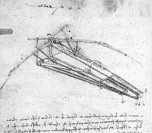
Figure 1.1. Da Vinci’s flying machine
1.2 Brief Historical Background
This section provides a compressed tour of history, which I hope will motivate individuals to explore human aerial achievements in more detail. Many books cover the broad sweep of aeronautical history and many others depict particular cases such as famous people and their achievements in aeronautics ([1] is a good place to start). Innumerable Web sites on these topics exist; simply enter keywords such as Airbus, Boeing, or anything that piques your curiosity.
The desire to become airborne is ancient and it is reflected in our imagination and dreams. In the West, Daedalus and Icarus of Greek mythology were the first aviators; in the East, there are even more ancient myths – with no crashes. In Indian mythology, Pakshiraj is a white stallion with wings; the Greeks had a flying horse called Pegasus; and the Swedes also have flying horses. Garuda of Indonesia – half man and half bird – is another example from the Ramayana epic. Middle Eastern and South Asiatic “flying carpets” are seen in many Western cartoons and films. These contraptions are fully aerobatic with the ability to follow terrain; there are no seat belts and they can land inside rooms as well as on rooftops. Recreational possibilities and military applications abound!
Unfortunately, history is somewhat more “down to earth” than mythology, with early pioneers leaping from towers and cliffs, only to leave the Earth in a different but predictable manner because they underestimated the laws of nature. Our dreams and imagination became reality only about 100 years ago on December 17, 1903, with the first heavier-than-air flight by the Wright brothers. Yet, man first landed on the Moon about three decades ago, less than 70 years after the first powered flight.
The first scientific attempts to design a mechanism for aerial navigation were by Leonardo da Vinci (1452–1519) – he was the true grandfather of modern aviation, even if none of his machines ever defied gravity (Figure 1.1). He sketched many contraptions in his attempt to make a mechanical bird. However, birds possess such refined design features that the human path into the skies could not take that route; da Vinci’s ideas contradicted the laws of nature.

1.2 Brief Historical Background |
3 |
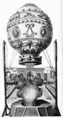
Figure 1.2. Montgolfier balloon
After da Vinci, and after an apparent lull for more than a century, the next prominent name is that of Sir Isaac Newton (1642–1727). Perhaps we lack the documentary evidence for I am convinced that human fascination with and endeavor for flight did not abate. Newton developed a theory of lift that although erroneous for low-speed flows, actually has some hypersonic application (although, of course, this was beyond his seventeenth-century understanding of fluid mechanics). Flight is essentially a practical matter, so real progress paralleled other industrial developments (e.g., isolating gas for buoyancy).
In 1783, de Rozier and d’Arlandes were the first to effectively defy gravity, using a Montgolfier (France) balloon (Figure 1.2). For the first time, it was possible to sustain and somewhat control altitude above the ground at will. However, these pioneers were subject to the prevailing wind direction and therefore were limited in their navigational options. To become airborne was an important landmark in human endeavor. The fact that the balloonists did not have wings does not diminish the importance of their achievement. The Montgolfier brothers (Joseph and Etienne) should be considered among the fathers of aviation. In 1784, Blanchard (France) added a hand-powered propeller to a balloon and was the first to make an aerial crossing of the English Channel on July 15, 1765. Jules Verne’s fictional trip around the world in eighty days in a balloon became a reality when Steve Fossett circumnavigated the globe in fewer than fifteen days in 2002 – approximately three centuries after the first balloon circumnavigation.
In 1855, Joseph Pline was the first to use the word aeroplane in a paper he wrote proposing a gas-filled dirigible glider with a propeller.
Tethered kites flew in the Far East for a long time – in China, 600 B.C. However, in 1804, Englishman Sir George Cayley constructed and flew a kite-like glider (Figure 1.3) with movable control surfaces – the first record of a successful heavier- than-air controllable machine to stay freely airborne. In 1842, English engineer Samuel Henson secured a patent on an aircraft design that was driven by a steam engine.
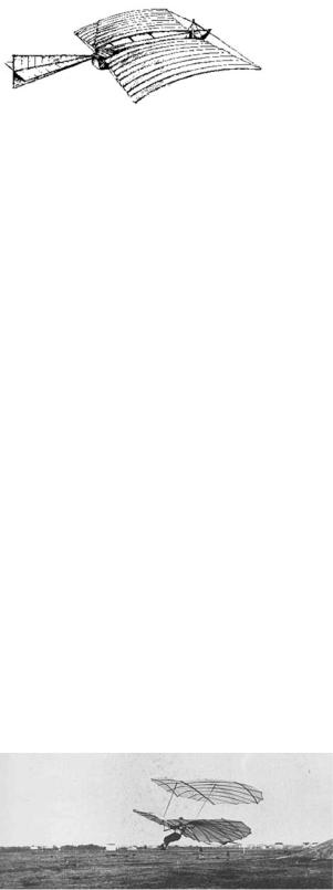
With his brother Gustav, Otto Lilienthal was successfully flying gliders (Figure 1.4) in Berlin more than a decade (ca. 1890) before the Wright brothers’ first

4 |
Introduction |
Figure 1.3. Cayley’s kite glider
experiments. His flights were controlled but not sustained. The overestimation of the power requirement for sustained flight (based on work by Sir Isaac Newton, among others) may have discouraged the attempts of the best enginemakers of the time in Germany to build an aircraft engine – it would have been too heavy. Sadly, Lilienthal’s aerial developments ended abruptly and his experience was lost when he died in a flying accident in 1896.
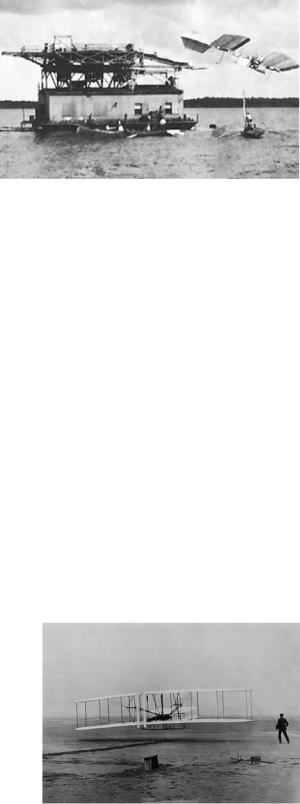
The question of who was the first to succeed naturally attracts a partisan spirit. The Wright Brothers (United States) are recognized as the first to achieve sustained, controlled flight of a heavier-than-air manned flying machine. Before discussing their achievement, however, some “also-rans” deserve mention (see various related Web sites). It is unfair not to credit John Stringfellow with the first powered flight of an unmanned heavier-than-air machine, made in 1848 in England. The Frenchman Ader also made a successful flight in his “Eole.” Gustav Weisskopf (Whitehead), a Bavarian who immigrated to the United States, claimed to have made a sustained, powered flight [2] on August 14, 1901, in Bridgeport, Connecticut. Karl Jatho of Germany made a 200-ft hop (longer than the Wright Brothers first flight) with a powered (10-HP Buchet engine) flight on August 18, 1903. At what distance a “hop” becomes a “flight” could be debated. Perhaps most significant are the efforts of Samuel P. Langley, who made three attempts to get his designs airborne with a pilot at the controls (Figure 1.5). His designs were aerodynamically superior to the Wright flyer, but the strategy to ensure pilot safety resulted in structural failure while catapulting from a ramp toward water. (A replica of Langley’s aircraft was successfully flown from a conventional takeoff.) His model aircraft were flying successfully since 1902. The breaking of the aircraft also broke Professor Langley – a short time afterward, he died of a heart attack. The Wright Brothers were mere bicycle mechanics without any external funding, whereas Professor Langley was a highly qualified scientist whose project had substantial government funding.
The discussion inevitably turns to the Wright Brothers. Their aircraft (Figure 1.6) was inherently unstable but – good bicycle manufacturers that they were – they understood that stability could be sacrificed if sufficient control authority was maintained. They employed a foreplane for pitch control, which also served as a stall-prevention device – as today’s Rutan-designed aircraft have demonstrated.
Figure 1.4. One of Lilienthal’s gliders

1.2 Brief Historical Background |
5 |
Figure 1.5. Langley’s catapult launch
Exactly a century later, a flying replica model of the Wright flyer failed to lift off on its first flight. The success of the Wright Brothers was attributed to a freak gust of wind to assist the liftoff. A full-scale nonflying replica of the Wright flyer is on display at the Smithsonian Museum in Washington, DC, and the exhibit and others are well worth a trip.
Strangely, the Wright Brothers did not exploit their invention; however, having been shown that sustained and controlled flight was possible, a new generation of aerial entrepreneurs quickly arose. Newer inventions followed in succession by pioneering names such as Santos Dumas, Bleriot, and Curtis, and the list grew rapidly. Each inventor presented a new contraption, some of which demonstrated genuine design improvements. Fame, adventure, and “Gefuhl¨” (feelings) were the drivers; the first few years barely demonstrated any financial gain except through “joy rides” and air shows – spectacles never seen before then and still just as appealing to the public now. It is interesting to observe the involvement of brothers from the eighteenth to the twentieth century – the Montgolfiers, du Temples, Lilienthas, and Wrights – perhaps they saw the future potential and wanted to keep progress confidential, and who can be better trusted than a brother?
It did not take long to demonstrate the advantages of aircraft, such as in mail delivery and military applications. At approximately 100 miles per hour (mph), on average, aircraft were traveling three times faster than any surface vehicle – and in straight lines. Mail was delivered in less than half the time. The potential for military applications was dramatic and well demonstrated during World War I. About a decade after the first flight in 1903, aircraft manufacturing had become a lucrative business. I am privileged to have started my own aeronautical engineering career
Figure 1.6. The Wright flyer
6 |
Introduction |
with Short Brothers and Harland (now part of the Bombardier Aerospace group), a company that started aircraft manufacturing by contracting to fabricate the Wright designs. The company is now the oldest surviving aircraft manufacturer still in operation. In 2008, it celebrated its centenary, the first aircraft company ever to do so.
The post–World War I aircraft industry geared up in defense applications and in civil aviation, with financial gain as the clear driver. The free-market economy of the West contributed much to aviation progress; its downside, possibly reflecting greed, was under-regulation. The proliferation showed signs of compromise with safety issues, and national regulatory agencies quickly stepped in, legislating for mandatory compliance with airworthiness requirements. Today, every nation has its own regulatory agency. The FAA in the United States and the Joint Aviation Authority (JAA) in Europe (recently renamed EASA) are the most recognized.
Early aircraft design was centered on available engines, and the size of the aircraft depended on the use of multiple engines. The predominant material used was wood. The combination of engines, materials, and aerodynamic technology enabled aircraft speeds of approximately 200 mph; altitude was limited by human physiology. Junker demonstrated the structural benefit of thick wing sections and metal construction. In the 1930s, Durener Metallwerke of Germany introduced duralumin, with higher strength-to-weight ratios of isotropic material properties, and dramatic increases in speed and altitude resulted. The introduction of metal brought a new dimension to manufacturing technology. Structure, aerodynamics, and engine development paved the way for substantial gains in speed, altitude, and maneuvering capabilities. These improvements were seen preeminently in World War II designs such as the Supermarine Spitfire, the North American P-51, the Focke Wolfe 190, and the Mitsubishi Jeero-Sen. Multiengine aircraft also grew to sizes never before seen.
The invention of the jet engine (independently by Whittle of the United Kingdom and von Ohain of Germany) realized the potential for unheard-of leaps in speed and altitude, resulting in parallel improvements in aerodynamics, materials, structures, and systems engineering. A better understanding of supersonic flow and a suitable rocket engine made it possible for Chuck Yeager to break the sound barrier in a Bell X1 in 1949. (The record-making aircraft is on exhibit at the Smithsonian Air and Space Museum in Washington, DC.)
Less glamorous multiengine heavy-lifters were slower in progress but with no less success. Tens of thousands of the Douglas C-47 Dakota and Boeing B17 Flying Fortress were produced. Postwar, the De Havilland Comet was the first commercial jet aircraft in service; however, plagued by several tragic crashes, it failed to become the financial success it promised. (The first Comet crash occurred at Dum Dum, near Calcutta, in 1952, in a monsoon storm. At that time, I lived about 12 miles from the crash site.)
The 1960s and 1970s saw rapid progress with many new commercial and military aircraft designs boasting ever-increasing speed, altitude, and payload capabilities. Scientists made considerable gains in understanding the relevant branches of nature: in aerodynamic [3] issues concerning high lift and transonic drag; in materials and metallurgy, improving the structural integrity; and in significant discoveries in solid-state physics. Engineers made good use of the new understanding. Some of the outstanding designs of those decades emerged from the Lockheed