

- •Contents
- •Symbols and Abbreviations
- •Symbols
- •Greek Symbols
- •Subscripts
- •Abbreviations
- •Preface
- •Road Map of the Book
- •The Arrangement
- •Suggested Route for the Coursework
- •First Semester
- •Second Semester
- •Suggestions for the Class
- •Use of Semi-empirical Relations
- •1 Introduction
- •1.1 Overview
- •1.1.1 What Is to Be Learned?
- •1.1.2 Coursework Content
- •1.2 Brief Historical Background
- •1.3 Current Aircraft Design Status
- •1.3.1 Forces and Drivers
- •1.3.2 Current Civil Aircraft Design Trends
- •1.3.3 Current Military Aircraft Design Trends
- •1.4 Future Trends
- •1.4.1 Civil Aircraft Design: Future Trends
- •1.4.2 Military Aircraft Design: Future Trends
- •1.5 Learning Process
- •1.6 Units and Dimensions
- •1.7 Cost Implications
- •2 Methodology to Aircraft Design, Market Survey, and Airworthiness
- •2.1 Overview
- •2.1.1 What Is to Be Learned?
- •2.1.2 Coursework Content
- •2.2 Introduction
- •2.3 Typical Design Process
- •2.3.1 Four Phases of Aircraft Design
- •2.3.2 Typical Resources Deployment
- •2.3.3 Typical Cost Frame
- •2.3.4 Typical Time Frame
- •2.4 Typical Task Breakdown in Each Phase
- •Phase 1: Conceptual Study Phase (Feasibility Study)
- •Phase 3: Detailed Design Phase (Full-Scale Product Development)
- •2.4.1 Functional Tasks during the Conceptual Study (Phase 1: Civil Aircraft)
- •2.4.2 Project Activities for Small Aircraft Design
- •Phase 1: Conceptual Design (6 Months)
- •Phase 3: Detailed Design (Product Development) (12 Months)
- •2.5 Aircraft Familiarization
- •Fuselage Group
- •Wing Group
- •Empennage Group
- •Nacelle Group
- •Undercarriage Group
- •2.6 Market Survey
- •2.7 Civil Aircraft Market
- •2.8 Military Market
- •2.9 Comparison between Civil and Military Aircraft Design Requirements
- •2.10 Airworthiness Requirements
- •2.11 Coursework Procedures
- •3 Aerodynamic Considerations
- •3.1 Overview
- •3.1.1 What Is to Be Learned?
- •3.1.2 Coursework Content
- •3.2 Introduction
- •3.3 Atmosphere
- •3.4 Fundamental Equations
- •3.5.1 Flow Past Aerofoil
- •3.6 Aircraft Motion and Forces
- •3.6.1 Motion
- •3.6.2 Forces
- •3.7 Aerofoil
- •3.7.1 Groupings of Aerofoils and Their Properties
- •NACA Four-Digit Aerofoil
- •NACA Five-Digit Aerofoil
- •NACA Six-Digit Aerofoil
- •Other Types of Aerofoils
- •3.9 Generation of Lift
- •3.10 Types of Stall
- •3.10.1 Gradual Stall
- •3.10.2 Abrupt Stall
- •3.11 Comparison of Three NACA Aerofoils
- •3.12 High-Lift Devices
- •3.13 Transonic Effects – Area Rule
- •3.14 Wing Aerodynamics
- •3.14.1 Induced Drag and Total Aircraft Drag
- •3.15 Aspect Ratio Correction of 2D Aerofoil Characteristics for 3D Finite Wing
- •3.16.1 Planform Area, SW
- •3.16.2 Wing Aspect Ratio
- •3.16.4 Wing Root (Croot) and Tip (Ctip) Chord
- •3.16.6 Wing Twist
- •3.17 Mean Aerodynamic Chord
- •3.18 Compressibility Effect: Wing Sweep
- •3.19 Wing Stall Pattern and Wing Twist
- •3.20.1 The Square-Cube Law
- •3.20.2 Aircraft Wetted Area (AW) versus Wing Planform Area (Sw)
- •3.20.3 Additional Vortex Lift
- •3.20.4 Additional Surfaces on Wing
- •3.21 Finalizing Wing Design Parameters
- •3.22 Empennage
- •3.22.1 H-Tail
- •3.22.2 V-Tail
- •3.23 Fuselage
- •3.23.2 Fuselage Length, Lfus
- •3.23.3 Fineness Ratio, FR
- •3.23.4 Fuselage Upsweep Angle
- •3.23.5 Fuselage Closure Angle
- •3.23.6 Front Fuselage Closure Length, Lf
- •3.23.7 Aft Fuselage Closure Length, La
- •3.23.8 Midfuselage Constant Cross-Section Length, Lm
- •3.23.9 Fuselage Height, H
- •3.23.10 Fuselage Width, W
- •3.23.11 Average Diameter, Dave
- •3.23.12 Cabin Height, Hcab
- •3.23.13 Cabin Width, Wcab
- •3.24 Undercarriage
- •3.25 Nacelle and Intake
- •3.26 Speed Brakes and Dive Brakes
- •4.1 Overview
- •4.1.1 What Is to Be Learned?
- •4.1.2 Coursework Content
- •4.2 Introduction
- •4.3 Aircraft Evolution
- •4.4 Civil Aircraft Mission (Payload-Range)
- •4.5 Civil Subsonic Jet Aircraft Statistics (Sizing Parameters and Regression Analysis)
- •4.5.1 Maximum Takeoff Mass versus Number of Passengers
- •4.5.2 Maximum Takeoff Mass versus Operational Empty Mass
- •4.5.3 Maximum Takeoff Mass versus Fuel Load
- •4.5.4 Maximum Takeoff Mass versus Wing Area
- •4.5.5 Maximum Takeoff Mass versus Engine Power
- •4.5.6 Empennage Area versus Wing Area
- •4.5.7 Wing Loading versus Aircraft Span
- •4.6 Civil Aircraft Component Geometries
- •4.7 Fuselage Group
- •4.7.1 Fuselage Width
- •4.7.2 Fuselage Length
- •4.7.3 Front (Nose Cone) and Aft-End Closure
- •4.7.4 Flight Crew (Flight Deck) Compartment Layout
- •4.7.5 Cabin Crew and Passenger Facilities
- •4.7.6 Seat Arrangement, Pitch, and Posture (95th Percentile) Facilities
- •4.7.7 Passenger Facilities
- •4.7.8 Cargo Container Sizes
- •4.7.9 Doors – Emergency Exits
- •4.8 Wing Group
- •4.9 Empennage Group (Civil Aircraft)
- •4.10 Nacelle Group
- •4.11 Summary of Civil Aircraft Design Choices
- •4.13 Military Aircraft Mission
- •4.14.1 Military Aircraft Maximum Take-off Mass (MTOM) versus Payload
- •4.14.2 Military MTOM versus OEM
- •4.14.3 Military MTOM versus Fuel Load Mf
- •4.14.4 MTOM versus Wing Area (Military)
- •4.14.5 MTOM versus Engine Thrust (Military)
- •4.14.6 Empennage Area versus Wing Area (Military)
- •4.14.7 Aircraft Wetted Area versus Wing Area (Military)
- •4.15 Military Aircraft Component Geometries
- •4.16 Fuselage Group (Military)
- •4.17 Wing Group (Military)
- •4.17.1 Generic Wing Planform Shapes
- •4.18 Empennage Group (Military)
- •4.19 Intake/Nacelle Group (Military)
- •4.20 Undercarriage Group
- •4.21 Miscellaneous Comments
- •4.22 Summary of Military Aircraft Design Choices
- •5 Aircraft Load
- •5.1 Overview
- •5.1.1 What Is to Be Learned?
- •5.1.2 Coursework Content
- •5.2 Introduction
- •5.2.1 Buffet
- •5.2.2 Flutter
- •5.3 Flight Maneuvers
- •5.3.1 Pitch Plane (X-Z) Maneuver (Elevator/Canard-Induced)
- •5.3.2 Roll Plane (Y-Z) Maneuver (Aileron-Induced)
- •5.3.3 Yaw Plane (Z-X) Maneuver (Rudder-Induced)
- •5.4 Aircraft Loads
- •5.4.1 On the Ground
- •5.4.2 In Flight
- •5.5.1 Load Factor, n
- •5.6 Limits – Load and Speeds
- •5.6.1 Maximum Limit of Load Factor
- •5.6.2 Speed Limits
- •5.7 V-n Diagram
- •5.7.1 Low-Speed Limit
- •5.7.2 High-Speed Limit
- •5.7.3 Extreme Points of a V-n Diagram
- •Positive Loads
- •Negative Loads
- •5.8 Gust Envelope
- •6.1 Overview
- •6.1.1 What Is to Be Learned?
- •6.1.2 Coursework Content
- •6.2 Introduction
- •Closure of the Fuselage
- •6.4 Civil Aircraft Fuselage: Typical Shaping and Layout
- •6.4.1 Narrow-Body, Single-Aisle Aircraft
- •6.4.2 Wide-Body, Double-Aisle Aircraft
- •6.4.3 Worked-Out Example: Civil Aircraft Fuselage Layout
- •6.5.1 Aerofoil Selection
- •6.5.2 Wing Design
- •Planform Shape
- •Wing Reference Area
- •Wing Sweep
- •Wing Twist
- •Wing Dihedral/Anhedral
- •6.5.3 Wing-Mounted Control-Surface Layout
- •6.5.4 Positioning of the Wing Relative to the Fuselage
- •6.6.1 Horizontal Tail
- •6.6.2 Vertical Tail
- •6.8 Undercarriage Positioning
- •6.10 Miscellaneous Considerations in Civil Aircraft
- •6.12.1 Use of Statistics in the Class of Military Trainer Aircraft
- •6.12.3 Miscellaneous Considerations – Military Design
- •6.13 Variant CAS Design
- •6.13.1 Summary of the Worked-Out Military Aircraft Preliminary Details
- •7 Undercarriage
- •7.1 Overview
- •7.1.1 What Is to Be Learned?
- •7.1.2 Coursework Content
- •7.2 Introduction
- •7.3 Types of Undercarriage
- •7.5 Undercarriage Retraction and Stowage
- •7.5.1 Stowage Space Clearances
- •7.6 Undercarriage Design Drivers and Considerations
- •7.7 Turning of an Aircraft
- •7.8 Wheels
- •7.9 Loads on Wheels and Shock Absorbers
- •7.9.1 Load on Wheels
- •7.9.2 Energy Absorbed
- •7.11 Tires
- •7.13 Undercarriage Layout Methodology
- •7.14 Worked-Out Examples
- •7.14.1 Civil Aircraft: Bizjet
- •Baseline Aircraft with 10 Passengers at a 33-Inch Pitch
- •Shrunk Aircraft (Smallest in the Family Variant) with 6 Passengers at a 33-Inch Pitch
- •7.14.2 Military Aircraft: AJT
- •7.15 Miscellaneous Considerations
- •7.16 Undercarriage and Tire Data
- •8 Aircraft Weight and Center of Gravity Estimation
- •8.1 Overview
- •8.1.1 What Is to Be Learned?
- •8.1.2 Coursework Content
- •8.2 Introduction
- •8.3 The Weight Drivers
- •8.4 Aircraft Mass (Weight) Breakdown
- •8.5 Desirable CG Position
- •8.6 Aircraft Component Groups
- •8.6.1 Civil Aircraft
- •8.6.2 Military Aircraft (Combat Category)
- •8.7 Aircraft Component Mass Estimation
- •8.8 Rapid Mass Estimation Method: Civil Aircraft
- •8.9 Graphical Method for Predicting Aircraft Component Weight: Civil Aircraft
- •8.10 Semi-empirical Equation Method (Statistical)
- •8.10.1 Fuselage Group – Civil Aircraft
- •8.10.2 Wing Group – Civil Aircraft
- •8.10.3 Empennage Group – Civil Aircraft
- •8.10.4 Nacelle Group – Civil Aircraft
- •Jet Type (Includes Pylon Mass)
- •Turboprop Type
- •Piston-Engine Nacelle
- •8.10.5 Undercarriage Group – Civil Aircraft
- •Tricycle Type (Retractable) – Fuselage-Mounted (Nose and Main Gear Estimated Together)
- •8.10.6 Miscellaneous Group – Civil Aircraft
- •8.10.7 Power Plant Group – Civil Aircraft
- •Turbofans
- •Turboprops
- •Piston Engines
- •8.10.8 Systems Group – Civil Aircraft
- •8.10.9 Furnishing Group – Civil Aircraft
- •8.10.10 Contingency and Miscellaneous – Civil Aircraft
- •8.10.11 Crew – Civil Aircraft
- •8.10.12 Payload – Civil Aircraft
- •8.10.13 Fuel – Civil Aircraft
- •8.11 Worked-Out Example – Civil Aircraft
- •8.11.1 Fuselage Group Mass
- •8.11.2 Wing Group Mass
- •8.11.3 Empennage Group Mass
- •8.11.4 Nacelle Group Mass
- •8.11.5 Undercarriage Group Mass
- •8.11.6 Miscellaneous Group Mass
- •8.11.7 Power Plant Group Mass
- •8.11.8 Systems Group Mass
- •8.11.9 Furnishing Group Mass
- •8.11.10 Contingency Group Mass
- •8.11.11 Crew Mass
- •8.11.12 Payload Mass
- •8.11.13 Fuel Mass
- •8.11.14 Weight Summary
- •Variant Aircraft in the Family
- •8.12 Center of Gravity Determination
- •8.12.1 Bizjet Aircraft CG Location Example
- •8.12.2 First Iteration to Fine Tune CG Position Relative to Aircraft and Components
- •8.13 Rapid Mass Estimation Method – Military Aircraft
- •8.14 Graphical Method to Predict Aircraft Component Weight – Military Aircraft
- •8.15 Semi-empirical Equation Methods (Statistical) – Military Aircraft
- •8.15.1 Military Aircraft Fuselage Group (SI System)
- •8.15.2 Military Aircraft Wing Mass (SI System)
- •8.15.3 Military Aircraft Empennage
- •8.15.4 Nacelle Mass Example – Military Aircraft
- •8.15.5 Power Plant Group Mass Example – Military Aircraft
- •8.15.6 Undercarriage Mass Example – Military Aircraft
- •8.15.7 System Mass – Military Aircraft
- •8.15.8 Aircraft Furnishing – Military Aircraft
- •8.15.11 Crew Mass
- •8.16.1 AJT Fuselage Example (Based on CAS Variant)
- •8.16.2 AJT Wing Example (Based on CAS Variant)
- •8.16.3 AJT Empennage Example (Based on CAS Variant)
- •8.16.4 AJT Nacelle Mass Example (Based on CAS Variant)
- •8.16.5 AJT Power Plant Group Mass Example (Based on AJT Variant)
- •8.16.6 AJT Undercarriage Mass Example (Based on CAS Variant)
- •8.16.7 AJT Systems Group Mass Example (Based on AJT Variant)
- •8.16.8 AJT Furnishing Group Mass Example (Based on AJT Variant)
- •8.16.9 AJT Contingency Group Mass Example
- •8.16.10 AJT Crew Mass Example
- •8.16.13 Weights Summary – Military Aircraft
- •8.17 CG Position Determination – Military Aircraft
- •8.17.1 Classroom Worked-Out Military AJT CG Location Example
- •8.17.2 First Iteration to Fine Tune CG Position and Components Masses
- •9 Aircraft Drag
- •9.1 Overview
- •9.1.1 What Is to Be Learned?
- •9.1.2 Coursework Content
- •9.2 Introduction
- •9.4 Aircraft Drag Breakdown (Subsonic)
- •9.5 Aircraft Drag Formulation
- •9.6 Aircraft Drag Estimation Methodology (Subsonic)
- •9.7 Minimum Parasite Drag Estimation Methodology
- •9.7.2 Computation of Wetted Areas
- •Lifting Surfaces
- •Fuselage
- •Nacelle
- •9.7.3 Stepwise Approach to Compute Minimum Parasite Drag
- •9.8 Semi-empirical Relations to Estimate Aircraft Component Parasite Drag
- •9.8.1 Fuselage
- •9.8.2 Wing, Empennage, Pylons, and Winglets
- •9.8.3 Nacelle Drag
- •Intake Drag
- •Base Drag
- •Boat-Tail Drag
- •9.8.4 Excrescence Drag
- •9.8.5 Miscellaneous Parasite Drags
- •Air-Conditioning Drag
- •Trim Drag
- •Aerials
- •9.9 Notes on Excrescence Drag Resulting from Surface Imperfections
- •9.10 Minimum Parasite Drag
- •9.12 Subsonic Wave Drag
- •9.13 Total Aircraft Drag
- •9.14 Low-Speed Aircraft Drag at Takeoff and Landing
- •9.14.1 High-Lift Device Drag
- •9.14.2 Dive Brakes and Spoilers Drag
- •9.14.3 Undercarriage Drag
- •9.14.4 One-Engine Inoperative Drag
- •9.15 Propeller-Driven Aircraft Drag
- •9.16 Military Aircraft Drag
- •9.17 Supersonic Drag
- •9.18 Coursework Example: Civil Bizjet Aircraft
- •9.18.1 Geometric and Performance Data
- •Fuselage (see Figure 9.13)
- •Wing (see Figure 9.13)
- •Empennage (see Figure 9.13)
- •Nacelle (see Figure 9.13)
- •9.18.2 Computation of Wetted Areas, Re, and Basic CF
- •Fuselage
- •Wing
- •Empennage (same procedure as for the wing)
- •Nacelle
- •Pylon
- •9.18.3 Computation of 3D and Other Effects to Estimate Component
- •Fuselage
- •Wing
- •Empennage
- •Nacelle
- •Pylon
- •9.18.4 Summary of Parasite Drag
- •9.18.5 CDp Estimation
- •9.18.6 Induced Drag
- •9.18.7 Total Aircraft Drag at LRC
- •9.19 Coursework Example: Subsonic Military Aircraft
- •9.19.1 Geometric and Performance Data of a Vigilante RA-C5 Aircraft
- •Fuselage
- •Wing
- •Empennage
- •9.19.2 Computation of Wetted Areas, Re, and Basic CF
- •Fuselage
- •Wing
- •Empennage (same procedure as for the wing)
- •9.19.3 Computation of 3D and Other Effects to Estimate Component CDpmin
- •Fuselage
- •Wing
- •Empennage
- •9.19.4 Summary of Parasite Drag
- •9.19.5 CDp Estimation
- •9.19.6 Induced Drag
- •9.19.7 Supersonic Drag Estimation
- •9.19.8 Total Aircraft Drag
- •9.20 Concluding Remarks
- •10 Aircraft Power Plant and Integration
- •10.1 Overview
- •10.1.1 What Is to Be Learned?
- •10.1.2 Coursework Content
- •10.2 Background
- •10.4 Introduction: Air-Breathing Aircraft Engine Types
- •10.4.1 Simple Straight-Through Turbojet
- •10.4.2 Turbofan: Bypass Engine
- •10.4.3 Afterburner Engine
- •10.4.4 Turboprop Engine
- •10.4.5 Piston Engine
- •10.6 Formulation and Theory: Isentropic Case
- •10.6.1 Simple Straight-Through Turbojet Engine: Formulation
- •10.6.2 Bypass Turbofan Engine: Formulation
- •10.6.3 Afterburner Engine: Formulation
- •10.6.4 Turboprop Engine: Formulation
- •Summary
- •10.7 Engine Integration with an Aircraft: Installation Effects
- •10.7.1 Subsonic Civil Aircraft Nacelle and Engine Installation
- •10.7.2 Turboprop Integration to Aircraft
- •10.7.3 Combat Aircraft Engine Installation
- •10.8 Intake and Nozzle Design
- •10.8.1 Civil Aircraft Intake Design: Inlet Sizing
- •10.8.2 Military Aircraft Intake Design
- •10.9 Exhaust Nozzle and Thrust Reverser
- •10.9.1 Civil Aircraft Thrust Reverser Application
- •10.9.2 Civil Aircraft Exhaust Nozzles
- •10.9.3 Coursework Example of Civil Aircraft Nacelle Design
- •Intake Geometry (see Section 10.8.1)
- •Lip Section (Crown Cut)
- •Lip Section (Keel Cut)
- •Nozzle Geometry
- •10.9.4 Military Aircraft Thrust Reverser Application and Exhaust Nozzles
- •10.10 Propeller
- •10.10.2 Propeller Theory
- •Momentum Theory: Actuator Disc
- •Blade-Element Theory
- •10.10.3 Propeller Performance: Practical Engineering Applications
- •Static Performance (see Figures 10.34 and 10.36)
- •In-Flight Performance (see Figures 10.35 and 10.37)
- •10.10.5 Propeller Performance at STD Day: Worked-Out Example
- •10.11 Engine-Performance Data
- •Takeoff Rating
- •Maximum Continuous Rating
- •Maximum Climb Rating
- •Maximum Cruise Rating
- •Idle Rating
- •10.11.1 Piston Engine
- •10.11.2 Turboprop Engine (Up to 100 Passengers Class)
- •Takeoff Rating
- •Maximum Climb Rating
- •Maximum Cruise Rating
- •10.11.3 Turbofan Engine: Civil Aircraft
- •Turbofans with a BPR Around 4 (Smaller Engines; e.g., Bizjets)
- •Turbofans with a BPR around 5 or 7 (Larger Engines; e.g., RJs and Larger)
- •10.11.4 Turbofan Engine – Military Aircraft
- •11 Aircraft Sizing, Engine Matching, and Variant Derivative
- •11.1 Overview
- •11.1.1 What Is to Be Learned?
- •11.1.2 Coursework Content
- •11.2 Introduction
- •11.3 Theory
- •11.3.1 Sizing for Takeoff Field Length
- •Civil Aircraft Design: Takeoff
- •Military Aircraft Design: Takeoff
- •11.3.2 Sizing for the Initial Rate of Climb
- •11.3.3 Sizing to Meet Initial Cruise
- •11.3.4 Sizing for Landing Distance
- •11.4 Coursework Exercises: Civil Aircraft Design (Bizjet)
- •11.4.1 Takeoff
- •11.4.2 Initial Climb
- •11.4.3 Cruise
- •11.4.4 Landing
- •11.5 Coursework Exercises: Military Aircraft Design (AJT)
- •11.5.1 Takeoff – Military Aircraft
- •11.5.2 Initial Climb – Military Aircraft
- •11.5.3 Cruise – Military Aircraft
- •11.5.4 Landing – Military Aircraft
- •11.6 Sizing Analysis: Civil Aircraft (Bizjet)
- •11.6.1 Variants in the Family of Aircraft Design
- •11.6.2 Example: Civil Aircraft
- •11.7 Sizing Analysis: Military Aircraft
- •11.7.1 Single-Seat Variant in the Family of Aircraft Design
- •11.8 Sensitivity Study
- •11.9 Future Growth Potential
- •12.1 Overview
- •12.1.1 What Is to Be Learned?
- •12.1.2 Coursework Content
- •12.2 Introduction
- •12.3 Static and Dynamic Stability
- •12.3.1 Longitudinal Stability: Pitch Plane (Pitch Moment, M)
- •12.3.2 Directional Stability: Yaw Plane (Yaw Moment, N)
- •12.3.3 Lateral Stability: Roll Plane (Roll Moment, L)
- •12.3.4 Summary of Forces, Moments, and Their Sign Conventions
- •12.4 Theory
- •12.4.1 Pitch Plane
- •12.4.2 Yaw Plane
- •12.4.3 Roll Plane
- •12.6 Inherent Aircraft Motions as Characteristics of Design
- •12.6.1 Short-Period Oscillation and Phugoid Motion
- •12.6.2 Directional and Lateral Modes of Motion
- •12.7 Spinning
- •12.8 Design Considerations for Stability: Civil Aircraft
- •12.9 Military Aircraft: Nonlinear Effects
- •12.10 Active Control Technology: Fly-by-Wire
- •13 Aircraft Performance
- •13.1 Overview
- •13.1.1 What Is to Be Learned?
- •13.1.2 Coursework Content
- •13.2 Introduction
- •13.2.1 Aircraft Speed
- •13.3 Establish Engine Performance Data
- •13.3.1 Turbofan Engine (BPR < 4)
- •Takeoff Rating (Bizjet): Standard Day
- •Maximum Climb Rating (Bizjet): Standard Day
- •Maximum Cruise Rating (Bizjet): Standard Day
- •13.3.2 Turbofan Engine (BPR > 4)
- •13.3.3 Military Turbofan (Advanced Jet Trainer/CAS Role – Very Low BPR) – STD Day
- •13.3.4 Turboprop Engine Performance
- •Takeoff Rating (Turboprop): Standard Day
- •Maximum Climb Rating (Turboprop): Standard Day
- •Maximum Cruise Rating (Turboprop): Standard Day
- •13.4 Derivation of Pertinent Aircraft Performance Equations
- •13.4.1 Takeoff
- •Balanced Field Length: Civil Aircraft
- •Takeoff Equations
- •13.4.2 Landing Performance
- •13.4.3 Climb and Descent Performance
- •Summary
- •Descent
- •13.4.4 Initial Maximum Cruise Speed
- •13.4.5 Payload Range Capability
- •13.5 Aircraft Performance Substantiation: Worked-Out Examples (Bizjet)
- •13.5.1 Takeoff Field Length (Bizjet)
- •Segment A: All Engines Operating up to the Decision Speed V1
- •Segment B: One-Engine Inoperative Acceleration from V1 to Liftoff Speed, VLO
- •Segment C: Flaring Distance with One Engine Inoperative from VLO to V2
- •Segment E: Braking Distance from VB to Zero Velocity (Flap Settings Are of Minor Consequence)
- •Discussion of the Takeoff Analysis
- •13.5.2 Landing Field Length (Bizjet)
- •13.5.3 Climb Performance Requirements (Bizjet)
- •13.5.4 Integrated Climb Performance (Bizjet)
- •13.5.5 Initial High-Speed Cruise (Bizjet)
- •13.5.7 Descent Performance (Bizjet)
- •13.5.8 Payload Range Capability
- •13.6 Aircraft Performance Substantiation: Military Aircraft (AJT)
- •13.6.2 Takeoff Field Length (AJT)
- •Distance Covered from Zero to the Decision Speed V1
- •Distance Covered from Zero to Liftoff Speed VLO
- •Distance Covered from VLO to V2
- •Total Takeoff Distance
- •Stopping Distance and the CFL
- •Distance Covered from V1 to Braking Speed VB
- •Verifying the Climb Gradient at an 8-Deg Flap
- •13.6.3 Landing Field Length (AJT)
- •13.6.4 Climb Performance Requirements (AJT)
- •13.6.5 Maximum Speed Requirements (AJT)
- •13.6.6 Fuel Requirements (AJT)
- •13.7 Summary
- •13.7.1 The Bizjet
- •14 Computational Fluid Dynamics
- •14.1 Overview
- •14.1.1 What Is to Be Learned?
- •14.1.2 Coursework Content
- •14.2 Introduction
- •14.3 Current Status
- •14.4 Approach to CFD Analyses
- •14.4.1 In the Preprocessor (Menu-Driven)
- •14.4.2 In the Flow Solver (Menu-Driven)
- •14.4.3 In the Postprocessor (Menu-Driven)
- •14.5 Case Studies
- •14.6 Hierarchy of CFD Simulation Methods
- •14.6.1 DNS Simulation Technique
- •14.6.2 Large Eddy Simulation (LES) Technique
- •14.6.3 Detached Eddy Simulation (DES) Technique
- •14.6.4 RANS Equation Technique
- •14.6.5 Euler Method Technique
- •14.6.6 Full-Potential Flow Equations
- •14.6.7 Panel Method
- •14.7 Summary
- •15 Miscellaneous Design Considerations
- •15.1 Overview
- •15.1.1 What Is to Be Learned?
- •15.1.2 Coursework Content
- •15.2 Introduction
- •15.2.1 Environmental Issues
- •15.2.2 Materials and Structures
- •15.2.3 Safety Issues
- •15.2.4 Human Interface
- •15.2.5 Systems Architecture
- •15.2.6 Military Aircraft Survivability Issues
- •15.2.7 Emerging Scenarios
- •15.3 Noise Emissions
- •Approach
- •Sideline
- •15.3.1 Summary
- •15.4 Engine Exhaust Emissions
- •15.5 Aircraft Materials
- •15.5.1 Material Properties
- •15.5.2 Material Selection
- •15.5.3 Coursework Overview
- •Civil Aircraft Design
- •Military Aircraft Design
- •15.6 Aircraft Structural Considerations
- •15.7 Doors: Emergency Egress
- •Coursework Exercise
- •15.8 Aircraft Flight Deck (Cockpit) Layout
- •15.8.1 Multifunctional Display and Electronic Flight Information System
- •15.8.2 Combat Aircraft Flight Deck
- •15.8.3 Civil Aircraft Flight Deck
- •15.8.4 Head-Up Display
- •15.8.5 Helmet-Mounted Display
- •15.8.6 Hands-On Throttle and Stick
- •15.8.7 Voice-Operated Control
- •15.9 Aircraft Systems
- •15.9.1 Aircraft Control Subsystem
- •15.9.2 Engine and Fuel Control Subsystems
- •Piston Engine Fuel Control System (The total system weight is approximately 1 to 1.5% of the MTOW)
- •Turbofan Engine Fuel Control System (The total system weight is approximately 1.5 to 2% of the MTOW)
- •Fuel Storage and Flow Management
- •15.9.3 Emergency Power Supply
- •15.9.4 Avionics Subsystems
- •Military Aircraft Application
- •Civil Aircraft Application
- •15.9.5 Electrical Subsystem
- •15.9.6 Hydraulic Subsystem
- •15.9.7 Pneumatic System
- •ECS: Cabin Pressurization and Air-Conditioning
- •Oxygen Supply
- •Anti-icing, De-icing, Defogging, and Rain-Removal Systems
- •Defogging and Rain-Removal Systems
- •15.9.8 Utility Subsystem
- •15.9.9 End-of-Life Disposal
- •15.10 Military Aircraft Survivability
- •15.10.1 Military Emergency Escape
- •15.10.2 Military Aircraft Stealth Consideration
- •15.11 Emerging Scenarios
- •Counterterrorism Design Implementation
- •Health Issues
- •Damage from Runway Debris
- •16 Aircraft Cost Considerations
- •16.1 Overview
- •16.1.1 What Is to Be Learned?
- •16.1.2 Coursework Content
- •16.2 Introduction
- •16.3 Aircraft Cost and Operational Cost
- •Operating Cost
- •16.4 Aircraft Costing Methodology: Rapid-Cost Model
- •16.4.1 Nacelle Cost Drivers
- •Group 1
- •Group 2
- •16.4.2 Nose Cowl Parts and Subassemblies
- •16.4.3 Methodology (Nose Cowl Only)
- •Cost of Parts Fabrication
- •Subassemblies
- •Cost of Amortization of the NRCs
- •16.4.4 Cost Formulas and Results
- •16.5 Aircraft Direct Operating Cost
- •16.5.1 Formulation to Estimate DOC
- •Aircraft Price
- •Fixed-Cost Elements
- •Trip-Cost Elements
- •16.5.2 Worked-Out Example of DOC: Bizjet
- •Aircraft Price
- •Fixed-Cost Elements
- •Trip-Cost Elements
- •OC of the Variants in the Family
- •17 Aircraft Manufacturing Considerations
- •17.1 Overview
- •17.1.1 What Is to Be Learned?
- •17.1.2 Coursework Content
- •17.2 Introduction
- •17.3 Design for Manufacture and Assembly
- •17.4 Manufacturing Practices
- •17.5 Six Sigma Concept
- •17.6 Tolerance Relaxation at the Wetted Surface
- •17.6.1 Sources of Aircraft Surface Degeneration
- •17.6.2 Cost-versus-Tolerance Relationship
- •17.7 Reliability and Maintainability
- •17.8 Design Considerations
- •17.8.1 Category I: Technology-Driven Design Considerations
- •17.8.2 Category II: Manufacture-Driven Design Considerations
- •17.8.3 Category III: Management-Driven Design Considerations
- •17.8.4 Category IV: Operator-Driven Design Considerations
- •17.9 “Design for Customer”
- •17.9.1 Index for “Design for Customer”
- •17.9.2 Worked-Out Example
- •Standard Parameters of the Baseline Aircraft
- •Parameters of the Extended Variant Aircraft
- •Parameters of the Shortened Variant Aircraft
- •17.10 Digital Manufacturing Process Management
- •Process Detailing and Validation
- •Resource Modeling and Simulation
- •Process Planning and Simulation
- •17.10.1 Product, Process, and Resource Hub
- •17.10.3 Shop-Floor Interface
- •17.10.4 Design for Maintainability and 3D-Based Technical Publication Generation
- •Midrange Aircraft (Airbus 320 class)
- •References
- •ROAD MAP OF THE BOOK
- •CHAPTER 1. INTRODUCTION
- •CHAPTER 3. AERODYNAMIC CONSIDERATIONS
- •CHAPTER 5. AIRCRAFT LOAD
- •CHAPTER 6. CONFIGURING AIRCRAFT
- •CHAPTER 7. UNDERCARRIAGE
- •CHAPTER 8. AIRCRAFT WEIGHT AND CENTER OF GRAVITY ESTIMATION
- •CHAPTER 9. AIRCRAFT DRAG
- •CHAPTER 10. AIRCRAFT POWER PLANT AND INTEGRATION
- •CHAPTER 11. AIRCRAFT SIZING, ENGINE MATCHING, AND VARIANT DERIVATIVE
- •CHAPTER 12. STABILITY CONSIDERATIONS AFFECTING AIRCRAFT CONFIGURATION
- •CHAPTER 13. AIRCRAFT PERFORMANCE
- •CHAPTER 14. COMPUTATIONAL FLUID DYNAMICS
- •CHAPTER 15. MISCELLANEOUS DESIGN CONSIDERATIONS
- •CHAPTER 16. AIRCRAFT COST CONSIDERATIONS
- •CHAPTER 17. AIRCRAFT MANUFACTURING CONSIDERATIONS
- •Index
10.6 Formulation and Theory: Isentropic Case |
329 |
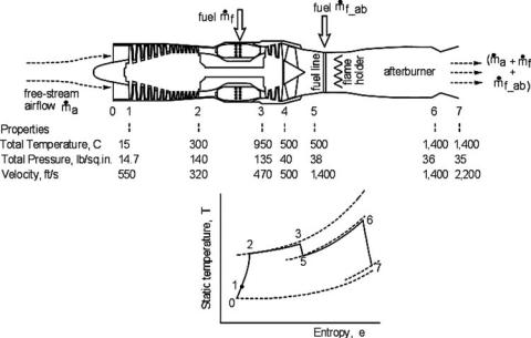
Figure 10.13. Afterburning turbojet and T-s diagram (real cycle)
Thus: |
|
|
|
|
(m˙ p + m˙ s ) × (Veq − V∞) = m˙ p × (Vep − V∞) + m˙ s × (Ves − V∞) |
|
|||
or |
(1 + BPR) × (Veq − V∞) = (Vep − V∞) + BPR × (Ves − V∞) |
|
||
or |
(1 + BPR) × Veq = (Vep − V∞) + BPR × (Ves − V∞) + V∞ × (1 + BPR) |
|||
|
= Vep + BPR × Ves |
|
||
or |
Veq = [Vep + BPR × Ves]/(1 + BPR) |
(10.18) |
||
Then, turbofan propulsive efficiency: |
|
|||
|
ηpf = |
2V∞ |
(10.19) |
|
|
Veq + V∞ |
|
||
Large engines could benefit from weight savings by installing short-duct turbofans; some smaller aircraft also use short-duct nacelles.
10.6.3 Afterburner Engine: Formulation
Figure 10.13 is a schematic diagram showing the station numbers for an AB jet engine. To keep numbers consistent with the turbojet numbering system, there is no difference between Stations 4 and 5, which represent the turbine exit condition. Station 5 is the start and Station 6 is the end of AB. Station 7 is the final exit plane. Figure 10.13 also shows the isentropic AB cycle in a T-s diagram.
AB is deployed only in military aircraft (except in the civil supersonic Concorde) as a temporary thrust-augmentation device to meet the mission demand at takeoff and/or fast acceleration and maneuvers to engage or disengage in combat. AB is applied at full throttle by activating a fuel switch. The pilot can feel the deployment by the sudden increase in the g-level in the flight direction. A ground observer