

202 |
Undercarriage |
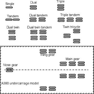
Figure 7.11. Wheel arrangements
7.8 Wheels
As an aircraft weight increases, the runway must bear the reaction and retain integrity to keep the vehicle’s field performance safe. Heavy commercial transport aircraft are intended to operate from a prepared runway (i.e., Types 2 and 3; see Section 7.10) to stay within the pavement strength; the load per wheel is restricted by distributing the total over several wheels. Various arrangements for more than one wheel per strut style are shown in Figure 7.11. Aircraft and undercarriage designers must plan for the number of struts, number of wheels per strut, and tire spacing and pressure (which determine the size) to distribute the load. As the aircraft MTOM increases, so does the number of wheels required, as well as considerations for stowing and articulation for retraction.
The fundamental wheel arrangements are single, twin, triple, and quadruple on a bogey. Wheel arrangements higher than a quadruple are not seen. The next level is their placement in a dual row as a single tandem, twin tandem (i.e., four wheels), triple tandem (i.e., six wheels), and so forth. The A380 wheel-arrangement model is shown in Figure 7.11. Figure 7.1 shows the wheel bogey of the world’s largest aircraft (i.e., the Antanov 225) with twin wheels per strut, for a total of seven struts.
7.9 Loads on Wheels and Shock Absorbers
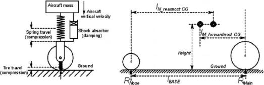
In its elementary representation, the undercarriage system acts as a spring-mass system, shown in Figure 7.12. Shock absorption is accomplished by its main spring and, to a smaller extent, by the tire pneumatics. Both spring and tire deflect under load. The oleo system acts as a damper; that is, it dissipates kinetic energy of vertical velocity. The strut can act as a spring for the lateral load of the ground friction.
The length of the strut is influenced by the extent that its shock absorber is compressed to the maximum. The minimum strut length is when both tire and shock
7.9 Loads on Wheels and Shock Absorbers |
203 |
Figure 7.12. Undercarriage as a spring-mass system
absorber collapse simultaneously, yet provide sufficient ground clearance for flaps fully extended (see Figure 7.8). The most critical situation for flap clearance is when the main wheel has collapsed and the nose wheel is at the fully extended position. (In a practical situation, the nose wheel tire would also remain deflected under load, but the margin of the fully extended position is safer.) The flap trailing edge is at its lowest at aircraft rotation for liftoff. A simultaneous failure of the tire and shock absorber after decision speed V1 (see Chapter 13) would force the pilot to continue with the aircraft rotation and liftoff.
During landing, as lift is depleting with speed reduction, more aircraft weight is reacting at the ground contact, which increases the spring load of the strut. The energy is stored in the spring. On brake application, the kinetic energy of the aircraft is absorbed by the brake pads, increasing temperature. If the limits are crossed with rapid deceleration, a fire hazard exists.
7.9.1 Load on Wheels
The load on the wheels determine the tire size. Wheel load is the aircraft weight distributed over the number of wheels. The aircraft CG position could vary depending on the extent of payload and fuel-load distribution; therefore, both the forwardmost and aftmost CG positions must be considered. (Table 7.4 provides an idea of the A380 load.)
As soon as the preliminary undercarriage information is known from the methodology described in this chapter, aircraft weights and the CG can be estimated through the formal procedure described Chapter 8.
Estimating the aftmost CG with the angle β ≈ 15 coinciding with 40% of the MAC gives a preliminary idea of the main-wheel position relative to the wing. The wing position relative to the fuselage could change when the formal weight and CG estimations are determined after the wing is sized. In that case, the wheel-load calculation must be revised. For transport aircraft design, at this stage, the forwardmost CG is 20 to 25% of the MAC ahead of the aftmost CG. For the nontransport category, including combat aircraft design, at this stage the forwardmost CG is 15% of the MAC ahead of the aftmost CG. The MTOW rather than the MTOM is used in the computation because the load is a force. (A simplified approach is to divide the mainand nose-wheel loads as 90 and 10% distribution, which has a
204 |
Undercarriage |
reasonable result, but the author recommends making the formal estimation at the beginning.)
Linear distance is represented by l with associated subscripts; R represents reaction forces. For more than one wheel, the load would then be divided accordingly. The force balance gives:
MTOW = 2 × RMAIN + RNOSE |
(7.1) |
To compute the maximum main-wheel load at the aftmost CG position, take the moment about the nose wheel. The moment equilibrium equation becomes:
lBASE × RMAIN = lN REAR CG × MTOW |
|
or RMAIN = (lN REAR CG × MTOW)/ lBASE |
(7.2) |
The load per strut on the main wheel is: |
|
LM = RMAIN /number of struts |
(7.3) |
To compute the maximum nose-wheel load at the forwardmost CG position, take the moment about the main wheel. The moment equilibrium equation becomes:
lBASE × RNOSE = lM FORWARD CG × MTOW |
|
or RNOSE = (lM FORWARD CG × MTOW)/ lBASE |
(7.4) |
The nose wheel typically has one strut.
Ensure that the load at the nose gear is not too high (i.e., no more than 20% of the MTOW) to avoid a high elevator load to rotate the aircraft for liftoff at takeoff. Also, it must not be too low – that is, not less than 8% of the MTOW; otherwise, there could be steering problems.
For more than one wheel per strut, the load per tire is calculated based on what each tire would produce on the same runway pavement stress at the same tire pressure as a single wheel. This is the equivalent single wheel load (ESWL) because loads are not shared equally when arranged side by side, unlike tandem arrangements. Wheel arrangements determine the ESWL as given here based on statistical means. Readers may consult the references for more details on other types of wheel arrangements.
The tandem twin wheel is:
ESWL = load per strut/2 |
(7.5) |
The side-by-side twin wheel is:
ESWL = load per strut/(1.5 to 1.33) (this book uses 1.5) |
(7.6) |
The tandem triple wheel is:
ESWL = load per strut/3 |
(7.7) |
The side-by-side triple wheel is:
ESWL = load per strut/(1.5 to 1.33) (this book uses 1.5) |
(7.8) |
7.9 Loads on Wheels and Shock Absorbers |
205 |
Table 7.1. Vertical speed |
|
|
|
|
|
VVert, = < 12 fps – FAR 23 (semi-empirical formula for exact rate, nl = 3) |
|
VVert, = < 12 fps – FAR 25 (nl = 2) |
|
VVert, = < 10 fps – Military transport (nl = 2) |
|
VVert, = < 13 fps – Military trainer (nl = maximum 5) |
|
VVert, = < 17 fps – Military land-based combat aircraft (nl = maximum 6) |
|
VVert, = < 22 fps – Military naval (aircraft-carrier)–based combat aircraft (nl = 8) |
|
The twin tandem is |
|
ESWL = load per strut/(3 to 2.67) |
(7.9) |
The main-wheel loads are calculated based on the aftmost CG position and the nosewheel loads are based on the forwardmost CG position. The dynamic load on the wheel is 50% higher than the static load.
7.9.2 Energy Absorbed
Both the tire and the shock absorber absorb the energy to cushion the impact of an aircraft’s vertical descent rate at landing in order to maintain structural integrity and avoid the tire bottoming out. FAA safety requirements limit the vertical descent velocity, VVert, for civil aircraft applications; military specifications limit military applications. Table 7.1 lists limits for various types of aircraft. In turn, VVert produces g-load at the sudden termination of VVert at landing – it can be expressed as load factor n (see Section 5.5). Equation 5.4 gives n = (1 + a/g); it is loosely termed as the number of the g-load; for an undercarriage design, it is designated n1 (see Table 7.1). During landing, nl takes a positive value; that is, it would experience heavier weight. For example,
nl = x (a number) means that the weight has changed by x times. |
(7.10) |
These are extreme values for safety; in practice, 4 fps is a hard landing in a civil aircraft operation. The maximum landing aircraft mass ML is taken as 0.95 MTOM for aircraft with a high wing-loading.
The vertical velocity kinetic energy to be absorbed is
Eab = 1/2ML × VVert |
2 |
(7.11) |
|
This is the energy to be absorbed by all the main wheels (m wheels) and struts (n struts) at touchdown during landing. The nose wheel touches the ground much later, after the main wheels have already absorbed the impact of landing.
Eab = Eab strut + Eab tire |
(7.12) |
ENERGY ABSORPTION BY STRUT (Let n be the number of struts.)
Assume that a landing is even and all struts have equal deflection of δstrut. Then, energy absorbed by all the struts is
Eab strut = n × nl × gML × kstrut × δstrut, |
(7.13) |
where kstrut is an efficiency factor representing the stiffness of the spring and has values between 0.5 and 0.8, depending on the type of shock absorber used.

206 |
Undercarriage |
In this book, 0.7 is used for modern aircraft and 0.5 is used for small club and homebuilt categories.
ENERGY ABSORPTION BY TIRE (Let m be the number of tires.)
Assume that a landing is even and all tires have equal deflection of δtire. Then, energy absorbed by all the tires is
Eab tire = m × nl × gML × ktire × δtire |
(7.14) |
where ktire = 0.47 is an efficiency factor representing the stiffness of all types of tires.
The following can be written by equating Equation 7.11 with Equation 7.12 and then substituting Equations 7.13 and 7.14 in Equation 7.12 and replacing nl by Equation 7.10. Here, the load factor nl is replaced by x:
Eab = 1/2ML × VVert2 = n × x × gML × kstrut × δstrut + m × x × gML × ktire × δtire
Simplifying as follows:
1/2 × VVert2 /g = x×(n × kstrut × δstrut + m × ktire × δtire) |
(7.15) |
7.9.3 Deflection under Load
The total vertical deflection of the strut and tire during landing can be computed by using Equation 7.15. Other types of lateral strut deflection during turning and other maneuvers are not addressed in this book.
Total deflection is
δ = δstrut + δtire |
(7.16) |
It is recommended that a cushion be kept in the strut deflection (compression) so that ends do not hit each other. In general, 1 inch (2.54 cm) is the margin.
7.10 Runway Pavement Classification
The undercarriage design depends on how the wheels interact with the airfield surface. An airport runway surface must be designed to withstand an aircraft’s weight not only at the static condition but also at dynamic loading (e.g., for a heavy landing). Runway pavement loading is known as flotation. Among airports, the runway pavement strength varies. There are three main types of surfaces, as follows:
1.Type 1: Unprepared Surface. A grass field or a gravel field, for example, is designated as a Type 1 surface. These are soft runways that are prone to depressions under a heavy load. Low-pressure tires with a maximum 45 to 60 lb per square inch (psi) and a total ESWL load less than 10,000 lb are the limits of operation on a soft runway. The ground friction is the highest and these airfields are not necessarily long. This type of runway is the least expensive to prepare and they serve remote areas, as an additional airfield close to a business center, or as a private airfield. Small utility aircraft can operate from Type 1 airfields.
7.10 Runway Pavement Classification |
|
|
207 |
|||
Table 7.2. Load classification group |
|
|
|
|
||
|
|
|
|
|
|
|
|
|
|
|
|
|
|
LCN range |
LCG |
LCN range |
LCG |
LCN range |
LGG |
|
|
|
|
|
|
|
|
101 to 120 |
I |
31 to 50 |
IV |
11 to 15 |
VI |
|
76 to 100 |
II |
16 to 30 |
V |
10 and below |
VII |
|
51 to 75 |
III |
|
|
|
|
|
|
|
|
|
|
|
|
2.Type 2: Prepared Macadam Surface. These are asphaltor tar-topped runways with strength built in by the thick macadam filler; these are designated as a Type 2 surface. These surfaces are less expensive to prepare by using a heavily rolled macadam filler. However, local depressions can cause the surface to undulate, and it requires frequent maintenance with longer downtime. This type of runway can accommodate heavy aircraft such as the B747.
3.Type 3: Prepared Concrete Surface. This is a rigid concrete runway designated as a Type 3 surface. These runways are built with pavement-quality concrete (i.e., about a half-meter thick) and are covered by asphalt (e.g., 150 mm thick). All major international airports have Type 3 runways, which can take a load similar to a Type 2 surface and do not have to be as thick. This type is expensive to prepare and maintenance downtime is minimal. Cracks are the typical type of failure that occurs. A Type 3 surface can accommodate heavy aircraft such as the B747 and the A380.
Aircraft designers must design aircraft to be compatible with existing airfields in order to operate. If the market demand necessitates larger and heavier aircraft, then designers must make the aircraft comply with the pavement strength of existing airfields or the airfield must be reinforced to accept the heavy aircraft. Runway reinforcement depends on new designs; therefore, airport authorities communicate with aircraft manufacturers to remain current with market demand. When the B747 began operating, almost all international airfields needed reinforcement to accept them – some were not operational for several years.
7.10.1 Load Classification Number Method
The ICAO, as an international agency, established ground rules to match aircraft and runway performance requirements. The ICAO developed the strength classifications of Type 2 and Type 3 runways by designating a load classification number (LCN) that represents the extent of load that a runway can accommodate based on construction characteristics. All Type 2 and Type 3 runways must have a LCN and the aircraft undercarriage design must comply with it. The LCN range of the airfield’s type is grouped under the load classification group (LCG). For example, an aircraft with the LCN 62 can operate on any airfield with an LCG of I to III. Table 7.2 provides the LCN range for the types of runways.
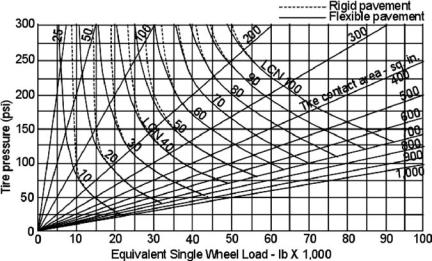
The relationship among the LCN, tire pressure, and ESWL is presented in Figure 7.13. The procedure is to first obtain the LCN of the airfield in question. Then, compute the ESWL of the undercarriage (see Section 7.9). Finally, find the tire pressure required using Table 7.6 (see Section 7.11); this provides a guideline to choose tire size. Section 7.13 outlines the methodology followed by worked-out
208 |
|
|
|
Undercarriage |
|
|
Table 7.3. Aircraft weight to comply with LCN and corresponding tire pressure |
||||
|
|
|
|
|
|
|
|
|
|
|
|
|
Aircraft |
MTOM (lb) |
Tire pressure (psi) |
LCN |
|
|
|
|
|
|
|
|
Fokker F27 |
45,000 |
80 |
19 |
|
|
McDonnell DC-9 |
65,000 |
129 |
39 |
|
|
B737–200 |
110,000 |
162 |
49 |
|
|
B757 |
210,000 |
157 |
50 |
|
|
B707 |
300,000 |
180 |
80 |
|
|
|
|
|
|
|
examples (see the references for more details on other types). Typical examples of aircraft complying with the LCN and the corresponding MTOM and tire pressures are given in Table 7.3.
The B757, which is twice as heavy as the B737, maintains nearly the same LCN by having more wheels to distribute load per tire.
7.10.2 Aircraft Classification Number and Pavement
Classification Number Method
The LCN is airfield-specific and aircraft must comply with it. Subsequently, ICAO introduced a new classification system, known as the aircraft classification number (ACN), which represents the tire-loading limit, and another system that represents the airfield pavement-strength limit, known as the pavement classification number (PCN). Both numbers must be the same to operate at an airport without any restrictions. However, the LCN method is still in use and conversion is needed to use the ACN/PCN method. This book uses Figure 7.13 to obtain the LCN.
The ACN/PCN method is described in [9]. According to the design manual, the ACN/PCN method is intended only for publication of pavement-strength data in the Aeronautical Information Publication (AIP). It is not intended for design or
Figure 7.13. Equivalent single-wheel load versus LCN