

7.2 Introduction |
193 |
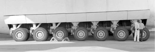
Figure 7.1. Antanov 225 (Mriya) main undercarriage
7.2 Introduction
The undercarriage, also known as the landing gear, is an essential aircraft component for the following functions: (1) support the aircraft when in place or towed, (2) taxi and steer on the ground using an aircraft’s own power, (3) the takeoff run, and
(4) landing and braking on the runway. For these reasons, the author prefers the term undercarriage rather than landing gear because the functions encompass more than mere landings. Once an aircraft is airborne, the undercarriage becomes redundant – an appendage that causes drag that can be minimized through retraction.
The undercarriage is seen as a subsystem consisting of a strong support spindle (i.e., strut) with a heavy-duty shock absorber to tackle heavy landings due to a rapid descent, whether inadvertently or on the short runway length of an aircraftcarrier ship. The undercarriage has a steering mechanism with shimmy control (i.e., control of dynamic instability; wheel oscillation about the support shaft and strut axis). The wheels have heavy-duty brakes that cause the temperature to reach high levels, resulting in a potential fire hazard. Heavy braking requires heavy-duty tires, which wear out quickly and are frequently replaced with new ones. Most undercarriages are designed to retract; the longer ones have articulated folding kinematics at retraction. The undercarriage retraction mechanism has hydraulic actuation; smaller aircraft may get by with an electrical motor drive.
The undercarriage is a complex system – the main undercarriage of the world’s largest aircraft (i.e., Antanov 225) is shown in Figure 7.1 (note the relative size of the people in the photograph). It is a bogey system (see Section 7.3) carrying 7 struts (i.e., support shafts with shock absorbers) per side, each carrying 2 wheels for a total of 32 wheels when the 4 nose wheels are added (2 × 2 × 7 + 4 = 32).
The undercarriage stowage bay within the aircraft is compactly sized to the extent that articulation allows. The stowage bay is located in the wing and/or the fuselage, or sometimes in the wing-mounted nacelles, depending on the realistic details of the design considered by aircraft designers at the conceptual stage. It is a challenging task for structural designers to establish a satisfactory design that integrates all the relationships and functionality of the undercarriage with the airframe. The author recommends keeping the undercarriage layout design as simple as possible for better reliability and maintainability without using too much of the articulation and/or stowage space in an aircraft. Reference 7.4 provides more details.
194 |
Undercarriage |
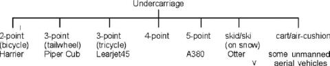
Chart 7.1. Undercarriage types (land-based)
A large aircraft is heavy enough to damage a metal runway; therefore, its weight is distributed over many wheels on a bogey system, which itself has articulation for retraction. The undercarriage mass can encompass as much as 7% (typically 4 to 5%) of the MTOM for large aircraft, it can weigh up to 3 tons with a corresponding cost of up to 5% of the aircraft total price, and the drag can be 10 to 20% of the total aircraft drag, depending on the size – smaller aircraft have a higher percentage of drag. For small, low-speed aircraft with a low-cost fixed undercarriage without a streamlined shroud, the drag could be as high as nearly a third of the total aircraft drag.
The undercarriage design should be based on the most critical configuration in the family of derivative aircraft offered. Generally, it is the longest one and therefore the heaviest, requiring the longest strut to clear the aft fuselage at maximum rotation. For the smaller version of the family, minor modifications assist in weight savings, yet retain a considerable amount of component commonality that reduces cost. In general, tires are the same size for all variants.
Other special types of undercarriages are not addressed herein. Today, all “flying boats” are amphibians with a retractable undercarriage. Undercarriage types are classified in the next section. Section 7.15 provides statistics. The Harrier VTOL/STOL and B52 aircraft have a bicycle-type undercarriage. These are difficult decisions for designers because there are no easier options other than the bicycle type, which requires an outrigger support wheel to prevent the wing from tipping at the sides. Aircraft with skids are intended for application on snow (the skids are mounted on or replace the wheels) or for gliders operating on grass fields. Some “tail-draggers” get by with using a skid instead of a tail wheel. Special designs use takeoff carts to get airborne; however, landing is another matter.
7.3 Types of Undercarriage
The undercarriage has an attachment point to the aircraft and can have more than one strut (i.e., support point). Chart 7.1 classifies various types in an elementary way, as if each support point has one strut with one wheel, with designations similar to a common bicycle. For example, the Airbus 380 aircraft has five support points (i.e., one nose wheel, two fuselage-mounted wheels, and two wing-mounted wheels) (see Figure 7.11) and many wheels and struts.
A nose wheel-type tricycle undercarriage is, by far, the dominant type, which is the type addressed in this book. The tail wheel type (i.e., fixed undercarriage) causes less drag, which can increase aircraft speed by 2 to 3%. However, on the ground, the raised nose impairs forward visibility and is more prone to “ground looping”
7.4 Undercarriage Layout, Nomenclature, and Definitions |
195 |
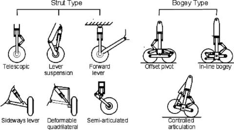
Figure 7.2. Undercarriage strut and bogey types
(described in Section 7.7). Currently, tail wheels are adapted for some lighter aircraft.
The simplest form of undercarriage was the earliest rigid axle type not in use any longer. Some form of shock absorber is favored nowadays. Struts with shock absorbers also are designed in many variations, as shown in Figure 7.2. When one strut has more than one wheel, it is seen as a bogey, as shown in the figure. There is a range of bogey designs not included in the figure.
7.4 Undercarriage Layout, Nomenclature, and Definitions
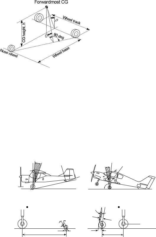
The position of the aircraft CG is a most important consideration when laying out wheel locations relative to an aircraft. Basically, the undercarriage consists of wheels on struts attached to aircraft points. The geometric parameters in placing wheels relative to the aircraft CG position are shown in Figure 7.3, along with the basic nomenclature of related parameters. The geometric definitions are as follows:
Wheel Base: The distance between the front and rear wheel axles in the vertical plane of symmetry
Wheel Tread or Wheel Track: The distance between the main wheels in the lateral plane of the aircraft
The wheel base and wheel track determine the aircraft turning radius (see Section 7.7) on the ground. The forwardmost aircraft CG position relative to the wheel base and wheel track determines the aircraft over-turn characteristics. The overturn angle, θ , is the maximum angle for a tilted aircraft with the CG on top of a main wheel; beyond that, the aircraft would turn over on its side. Determination of the angle θ is shown in Figure 7.3. Over-turn tipping is not exactly around the X-axis (i.e., sideways) when a low-wing aircraft could have a wing tip touching the ground before θ is reached. The tipping occurs about the axis joining the nose-wheel and main-wheel ground contact point, when the wing LE is likely to hit the ground.
196 |
Undercarriage |
Figure 7.3. Aircraft CG position relative to the undercarriage layout
It is better to maintain a lower angle θ to avoid an aircraft turning over; the value depends on the airfield surface, and the tendency increases with higher sideways ground friction. For simplification yet still representative, typical values used in this book follow (see the references for more details). For a paved runway, keep the angle θ less than 60 deg; for an unprepared field, it should be less than 50 deg. There are aircraft with θ = 35. Most of the aircraft have a θ between 40 and 50 deg.
An aircraft also can tip backwards if its rearmost CG goes behind the main wheel of a tricycle-type undercarriage; it can tip forward if its CG is in front of the main wheels of a tail-wheeled aircraft (Figure 7.4).
Definitions of the related parameters concerning wheel and strut provided in Figure 7.5 are more pertinent to the nose wheel ahead of the aircraft CG. These are not critical items at the conceptual design phase and can be omitted from the coursework. In the industry, these parameters are considered at an early stage.
CG range
CG
Tail clearance
Propeller
clearance Tail-wheel type
Ground
CG
range Aftmost CG
90 |
deg |
|
Nose-wheel type
Forwardmost CG
Rake angle
 Offset
Ground
Trail
Wheel base
Caster
angle |
Aftmost CG |
|
|
|
Offset |
Rolling radius
Trail
Wheel base
Figure 7.4. Undercarriage layout and nomenclature