
- •Contents
- •Symbols and Abbreviations
- •Symbols
- •Greek Symbols
- •Subscripts
- •Abbreviations
- •Preface
- •Road Map of the Book
- •The Arrangement
- •Suggested Route for the Coursework
- •First Semester
- •Second Semester
- •Suggestions for the Class
- •Use of Semi-empirical Relations
- •1 Introduction
- •1.1 Overview
- •1.1.1 What Is to Be Learned?
- •1.1.2 Coursework Content
- •1.2 Brief Historical Background
- •1.3 Current Aircraft Design Status
- •1.3.1 Forces and Drivers
- •1.3.2 Current Civil Aircraft Design Trends
- •1.3.3 Current Military Aircraft Design Trends
- •1.4 Future Trends
- •1.4.1 Civil Aircraft Design: Future Trends
- •1.4.2 Military Aircraft Design: Future Trends
- •1.5 Learning Process
- •1.6 Units and Dimensions
- •1.7 Cost Implications
- •2 Methodology to Aircraft Design, Market Survey, and Airworthiness
- •2.1 Overview
- •2.1.1 What Is to Be Learned?
- •2.1.2 Coursework Content
- •2.2 Introduction
- •2.3 Typical Design Process
- •2.3.1 Four Phases of Aircraft Design
- •2.3.2 Typical Resources Deployment
- •2.3.3 Typical Cost Frame
- •2.3.4 Typical Time Frame
- •2.4 Typical Task Breakdown in Each Phase
- •Phase 1: Conceptual Study Phase (Feasibility Study)
- •Phase 3: Detailed Design Phase (Full-Scale Product Development)
- •2.4.1 Functional Tasks during the Conceptual Study (Phase 1: Civil Aircraft)
- •2.4.2 Project Activities for Small Aircraft Design
- •Phase 1: Conceptual Design (6 Months)
- •Phase 3: Detailed Design (Product Development) (12 Months)
- •2.5 Aircraft Familiarization
- •Fuselage Group
- •Wing Group
- •Empennage Group
- •Nacelle Group
- •Undercarriage Group
- •2.6 Market Survey
- •2.7 Civil Aircraft Market
- •2.8 Military Market
- •2.9 Comparison between Civil and Military Aircraft Design Requirements
- •2.10 Airworthiness Requirements
- •2.11 Coursework Procedures
- •3 Aerodynamic Considerations
- •3.1 Overview
- •3.1.1 What Is to Be Learned?
- •3.1.2 Coursework Content
- •3.2 Introduction
- •3.3 Atmosphere
- •3.4 Fundamental Equations
- •3.5.1 Flow Past Aerofoil
- •3.6 Aircraft Motion and Forces
- •3.6.1 Motion
- •3.6.2 Forces
- •3.7 Aerofoil
- •3.7.1 Groupings of Aerofoils and Their Properties
- •NACA Four-Digit Aerofoil
- •NACA Five-Digit Aerofoil
- •NACA Six-Digit Aerofoil
- •Other Types of Aerofoils
- •3.9 Generation of Lift
- •3.10 Types of Stall
- •3.10.1 Gradual Stall
- •3.10.2 Abrupt Stall
- •3.11 Comparison of Three NACA Aerofoils
- •3.12 High-Lift Devices
- •3.13 Transonic Effects – Area Rule
- •3.14 Wing Aerodynamics
- •3.14.1 Induced Drag and Total Aircraft Drag
- •3.15 Aspect Ratio Correction of 2D Aerofoil Characteristics for 3D Finite Wing
- •3.16.1 Planform Area, SW
- •3.16.2 Wing Aspect Ratio
- •3.16.4 Wing Root (Croot) and Tip (Ctip) Chord
- •3.16.6 Wing Twist
- •3.17 Mean Aerodynamic Chord
- •3.18 Compressibility Effect: Wing Sweep
- •3.19 Wing Stall Pattern and Wing Twist
- •3.20.1 The Square-Cube Law
- •3.20.2 Aircraft Wetted Area (AW) versus Wing Planform Area (Sw)
- •3.20.3 Additional Vortex Lift
- •3.20.4 Additional Surfaces on Wing
- •3.21 Finalizing Wing Design Parameters
- •3.22 Empennage
- •3.22.1 H-Tail
- •3.22.2 V-Tail
- •3.23 Fuselage
- •3.23.2 Fuselage Length, Lfus
- •3.23.3 Fineness Ratio, FR
- •3.23.4 Fuselage Upsweep Angle
- •3.23.5 Fuselage Closure Angle
- •3.23.6 Front Fuselage Closure Length, Lf
- •3.23.7 Aft Fuselage Closure Length, La
- •3.23.8 Midfuselage Constant Cross-Section Length, Lm
- •3.23.9 Fuselage Height, H
- •3.23.10 Fuselage Width, W
- •3.23.11 Average Diameter, Dave
- •3.23.12 Cabin Height, Hcab
- •3.23.13 Cabin Width, Wcab
- •3.24 Undercarriage
- •3.25 Nacelle and Intake
- •3.26 Speed Brakes and Dive Brakes
- •4.1 Overview
- •4.1.1 What Is to Be Learned?
- •4.1.2 Coursework Content
- •4.2 Introduction
- •4.3 Aircraft Evolution
- •4.4 Civil Aircraft Mission (Payload-Range)
- •4.5 Civil Subsonic Jet Aircraft Statistics (Sizing Parameters and Regression Analysis)
- •4.5.1 Maximum Takeoff Mass versus Number of Passengers
- •4.5.2 Maximum Takeoff Mass versus Operational Empty Mass
- •4.5.3 Maximum Takeoff Mass versus Fuel Load
- •4.5.4 Maximum Takeoff Mass versus Wing Area
- •4.5.5 Maximum Takeoff Mass versus Engine Power
- •4.5.6 Empennage Area versus Wing Area
- •4.5.7 Wing Loading versus Aircraft Span
- •4.6 Civil Aircraft Component Geometries
- •4.7 Fuselage Group
- •4.7.1 Fuselage Width
- •4.7.2 Fuselage Length
- •4.7.3 Front (Nose Cone) and Aft-End Closure
- •4.7.4 Flight Crew (Flight Deck) Compartment Layout
- •4.7.5 Cabin Crew and Passenger Facilities
- •4.7.6 Seat Arrangement, Pitch, and Posture (95th Percentile) Facilities
- •4.7.7 Passenger Facilities
- •4.7.8 Cargo Container Sizes
- •4.7.9 Doors – Emergency Exits
- •4.8 Wing Group
- •4.9 Empennage Group (Civil Aircraft)
- •4.10 Nacelle Group
- •4.11 Summary of Civil Aircraft Design Choices
- •4.13 Military Aircraft Mission
- •4.14.1 Military Aircraft Maximum Take-off Mass (MTOM) versus Payload
- •4.14.2 Military MTOM versus OEM
- •4.14.3 Military MTOM versus Fuel Load Mf
- •4.14.4 MTOM versus Wing Area (Military)
- •4.14.5 MTOM versus Engine Thrust (Military)
- •4.14.6 Empennage Area versus Wing Area (Military)
- •4.14.7 Aircraft Wetted Area versus Wing Area (Military)
- •4.15 Military Aircraft Component Geometries
- •4.16 Fuselage Group (Military)
- •4.17 Wing Group (Military)
- •4.17.1 Generic Wing Planform Shapes
- •4.18 Empennage Group (Military)
- •4.19 Intake/Nacelle Group (Military)
- •4.20 Undercarriage Group
- •4.21 Miscellaneous Comments
- •4.22 Summary of Military Aircraft Design Choices
- •5 Aircraft Load
- •5.1 Overview
- •5.1.1 What Is to Be Learned?
- •5.1.2 Coursework Content
- •5.2 Introduction
- •5.2.1 Buffet
- •5.2.2 Flutter
- •5.3 Flight Maneuvers
- •5.3.1 Pitch Plane (X-Z) Maneuver (Elevator/Canard-Induced)
- •5.3.2 Roll Plane (Y-Z) Maneuver (Aileron-Induced)
- •5.3.3 Yaw Plane (Z-X) Maneuver (Rudder-Induced)
- •5.4 Aircraft Loads
- •5.4.1 On the Ground
- •5.4.2 In Flight
- •5.5.1 Load Factor, n
- •5.6 Limits – Load and Speeds
- •5.6.1 Maximum Limit of Load Factor
- •5.6.2 Speed Limits
- •5.7 V-n Diagram
- •5.7.1 Low-Speed Limit
- •5.7.2 High-Speed Limit
- •5.7.3 Extreme Points of a V-n Diagram
- •Positive Loads
- •Negative Loads
- •5.8 Gust Envelope
- •6.1 Overview
- •6.1.1 What Is to Be Learned?
- •6.1.2 Coursework Content
- •6.2 Introduction
- •Closure of the Fuselage
- •6.4 Civil Aircraft Fuselage: Typical Shaping and Layout
- •6.4.1 Narrow-Body, Single-Aisle Aircraft
- •6.4.2 Wide-Body, Double-Aisle Aircraft
- •6.4.3 Worked-Out Example: Civil Aircraft Fuselage Layout
- •6.5.1 Aerofoil Selection
- •6.5.2 Wing Design
- •Planform Shape
- •Wing Reference Area
- •Wing Sweep
- •Wing Twist
- •Wing Dihedral/Anhedral
- •6.5.3 Wing-Mounted Control-Surface Layout
- •6.5.4 Positioning of the Wing Relative to the Fuselage
- •6.6.1 Horizontal Tail
- •6.6.2 Vertical Tail
- •6.8 Undercarriage Positioning
- •6.10 Miscellaneous Considerations in Civil Aircraft
- •6.12.1 Use of Statistics in the Class of Military Trainer Aircraft
- •6.12.3 Miscellaneous Considerations – Military Design
- •6.13 Variant CAS Design
- •6.13.1 Summary of the Worked-Out Military Aircraft Preliminary Details
- •7 Undercarriage
- •7.1 Overview
- •7.1.1 What Is to Be Learned?
- •7.1.2 Coursework Content
- •7.2 Introduction
- •7.3 Types of Undercarriage
- •7.5 Undercarriage Retraction and Stowage
- •7.5.1 Stowage Space Clearances
- •7.6 Undercarriage Design Drivers and Considerations
- •7.7 Turning of an Aircraft
- •7.8 Wheels
- •7.9 Loads on Wheels and Shock Absorbers
- •7.9.1 Load on Wheels
- •7.9.2 Energy Absorbed
- •7.11 Tires
- •7.13 Undercarriage Layout Methodology
- •7.14 Worked-Out Examples
- •7.14.1 Civil Aircraft: Bizjet
- •Baseline Aircraft with 10 Passengers at a 33-Inch Pitch
- •Shrunk Aircraft (Smallest in the Family Variant) with 6 Passengers at a 33-Inch Pitch
- •7.14.2 Military Aircraft: AJT
- •7.15 Miscellaneous Considerations
- •7.16 Undercarriage and Tire Data
- •8 Aircraft Weight and Center of Gravity Estimation
- •8.1 Overview
- •8.1.1 What Is to Be Learned?
- •8.1.2 Coursework Content
- •8.2 Introduction
- •8.3 The Weight Drivers
- •8.4 Aircraft Mass (Weight) Breakdown
- •8.5 Desirable CG Position
- •8.6 Aircraft Component Groups
- •8.6.1 Civil Aircraft
- •8.6.2 Military Aircraft (Combat Category)
- •8.7 Aircraft Component Mass Estimation
- •8.8 Rapid Mass Estimation Method: Civil Aircraft
- •8.9 Graphical Method for Predicting Aircraft Component Weight: Civil Aircraft
- •8.10 Semi-empirical Equation Method (Statistical)
- •8.10.1 Fuselage Group – Civil Aircraft
- •8.10.2 Wing Group – Civil Aircraft
- •8.10.3 Empennage Group – Civil Aircraft
- •8.10.4 Nacelle Group – Civil Aircraft
- •Jet Type (Includes Pylon Mass)
- •Turboprop Type
- •Piston-Engine Nacelle
- •8.10.5 Undercarriage Group – Civil Aircraft
- •Tricycle Type (Retractable) – Fuselage-Mounted (Nose and Main Gear Estimated Together)
- •8.10.6 Miscellaneous Group – Civil Aircraft
- •8.10.7 Power Plant Group – Civil Aircraft
- •Turbofans
- •Turboprops
- •Piston Engines
- •8.10.8 Systems Group – Civil Aircraft
- •8.10.9 Furnishing Group – Civil Aircraft
- •8.10.10 Contingency and Miscellaneous – Civil Aircraft
- •8.10.11 Crew – Civil Aircraft
- •8.10.12 Payload – Civil Aircraft
- •8.10.13 Fuel – Civil Aircraft
- •8.11 Worked-Out Example – Civil Aircraft
- •8.11.1 Fuselage Group Mass
- •8.11.2 Wing Group Mass
- •8.11.3 Empennage Group Mass
- •8.11.4 Nacelle Group Mass
- •8.11.5 Undercarriage Group Mass
- •8.11.6 Miscellaneous Group Mass
- •8.11.7 Power Plant Group Mass
- •8.11.8 Systems Group Mass
- •8.11.9 Furnishing Group Mass
- •8.11.10 Contingency Group Mass
- •8.11.11 Crew Mass
- •8.11.12 Payload Mass
- •8.11.13 Fuel Mass
- •8.11.14 Weight Summary
- •Variant Aircraft in the Family
- •8.12 Center of Gravity Determination
- •8.12.1 Bizjet Aircraft CG Location Example
- •8.12.2 First Iteration to Fine Tune CG Position Relative to Aircraft and Components
- •8.13 Rapid Mass Estimation Method – Military Aircraft
- •8.14 Graphical Method to Predict Aircraft Component Weight – Military Aircraft
- •8.15 Semi-empirical Equation Methods (Statistical) – Military Aircraft
- •8.15.1 Military Aircraft Fuselage Group (SI System)
- •8.15.2 Military Aircraft Wing Mass (SI System)
- •8.15.3 Military Aircraft Empennage
- •8.15.4 Nacelle Mass Example – Military Aircraft
- •8.15.5 Power Plant Group Mass Example – Military Aircraft
- •8.15.6 Undercarriage Mass Example – Military Aircraft
- •8.15.7 System Mass – Military Aircraft
- •8.15.8 Aircraft Furnishing – Military Aircraft
- •8.15.11 Crew Mass
- •8.16.1 AJT Fuselage Example (Based on CAS Variant)
- •8.16.2 AJT Wing Example (Based on CAS Variant)
- •8.16.3 AJT Empennage Example (Based on CAS Variant)
- •8.16.4 AJT Nacelle Mass Example (Based on CAS Variant)
- •8.16.5 AJT Power Plant Group Mass Example (Based on AJT Variant)
- •8.16.6 AJT Undercarriage Mass Example (Based on CAS Variant)
- •8.16.7 AJT Systems Group Mass Example (Based on AJT Variant)
- •8.16.8 AJT Furnishing Group Mass Example (Based on AJT Variant)
- •8.16.9 AJT Contingency Group Mass Example
- •8.16.10 AJT Crew Mass Example
- •8.16.13 Weights Summary – Military Aircraft
- •8.17 CG Position Determination – Military Aircraft
- •8.17.1 Classroom Worked-Out Military AJT CG Location Example
- •8.17.2 First Iteration to Fine Tune CG Position and Components Masses
- •9 Aircraft Drag
- •9.1 Overview
- •9.1.1 What Is to Be Learned?
- •9.1.2 Coursework Content
- •9.2 Introduction
- •9.4 Aircraft Drag Breakdown (Subsonic)
- •9.5 Aircraft Drag Formulation
- •9.6 Aircraft Drag Estimation Methodology (Subsonic)
- •9.7 Minimum Parasite Drag Estimation Methodology
- •9.7.2 Computation of Wetted Areas
- •Lifting Surfaces
- •Fuselage
- •Nacelle
- •9.7.3 Stepwise Approach to Compute Minimum Parasite Drag
- •9.8 Semi-empirical Relations to Estimate Aircraft Component Parasite Drag
- •9.8.1 Fuselage
- •9.8.2 Wing, Empennage, Pylons, and Winglets
- •9.8.3 Nacelle Drag
- •Intake Drag
- •Base Drag
- •Boat-Tail Drag
- •9.8.4 Excrescence Drag
- •9.8.5 Miscellaneous Parasite Drags
- •Air-Conditioning Drag
- •Trim Drag
- •Aerials
- •9.9 Notes on Excrescence Drag Resulting from Surface Imperfections
- •9.10 Minimum Parasite Drag
- •9.12 Subsonic Wave Drag
- •9.13 Total Aircraft Drag
- •9.14 Low-Speed Aircraft Drag at Takeoff and Landing
- •9.14.1 High-Lift Device Drag
- •9.14.2 Dive Brakes and Spoilers Drag
- •9.14.3 Undercarriage Drag
- •9.14.4 One-Engine Inoperative Drag
- •9.15 Propeller-Driven Aircraft Drag
- •9.16 Military Aircraft Drag
- •9.17 Supersonic Drag
- •9.18 Coursework Example: Civil Bizjet Aircraft
- •9.18.1 Geometric and Performance Data
- •Fuselage (see Figure 9.13)
- •Wing (see Figure 9.13)
- •Empennage (see Figure 9.13)
- •Nacelle (see Figure 9.13)
- •9.18.2 Computation of Wetted Areas, Re, and Basic CF
- •Fuselage
- •Wing
- •Empennage (same procedure as for the wing)
- •Nacelle
- •Pylon
- •9.18.3 Computation of 3D and Other Effects to Estimate Component
- •Fuselage
- •Wing
- •Empennage
- •Nacelle
- •Pylon
- •9.18.4 Summary of Parasite Drag
- •9.18.5 CDp Estimation
- •9.18.6 Induced Drag
- •9.18.7 Total Aircraft Drag at LRC
- •9.19 Coursework Example: Subsonic Military Aircraft
- •9.19.1 Geometric and Performance Data of a Vigilante RA-C5 Aircraft
- •Fuselage
- •Wing
- •Empennage
- •9.19.2 Computation of Wetted Areas, Re, and Basic CF
- •Fuselage
- •Wing
- •Empennage (same procedure as for the wing)
- •9.19.3 Computation of 3D and Other Effects to Estimate Component CDpmin
- •Fuselage
- •Wing
- •Empennage
- •9.19.4 Summary of Parasite Drag
- •9.19.5 CDp Estimation
- •9.19.6 Induced Drag
- •9.19.7 Supersonic Drag Estimation
- •9.19.8 Total Aircraft Drag
- •9.20 Concluding Remarks
- •10 Aircraft Power Plant and Integration
- •10.1 Overview
- •10.1.1 What Is to Be Learned?
- •10.1.2 Coursework Content
- •10.2 Background
- •10.4 Introduction: Air-Breathing Aircraft Engine Types
- •10.4.1 Simple Straight-Through Turbojet
- •10.4.2 Turbofan: Bypass Engine
- •10.4.3 Afterburner Engine
- •10.4.4 Turboprop Engine
- •10.4.5 Piston Engine
- •10.6 Formulation and Theory: Isentropic Case
- •10.6.1 Simple Straight-Through Turbojet Engine: Formulation
- •10.6.2 Bypass Turbofan Engine: Formulation
- •10.6.3 Afterburner Engine: Formulation
- •10.6.4 Turboprop Engine: Formulation
- •Summary
- •10.7 Engine Integration with an Aircraft: Installation Effects
- •10.7.1 Subsonic Civil Aircraft Nacelle and Engine Installation
- •10.7.2 Turboprop Integration to Aircraft
- •10.7.3 Combat Aircraft Engine Installation
- •10.8 Intake and Nozzle Design
- •10.8.1 Civil Aircraft Intake Design: Inlet Sizing
- •10.8.2 Military Aircraft Intake Design
- •10.9 Exhaust Nozzle and Thrust Reverser
- •10.9.1 Civil Aircraft Thrust Reverser Application
- •10.9.2 Civil Aircraft Exhaust Nozzles
- •10.9.3 Coursework Example of Civil Aircraft Nacelle Design
- •Intake Geometry (see Section 10.8.1)
- •Lip Section (Crown Cut)
- •Lip Section (Keel Cut)
- •Nozzle Geometry
- •10.9.4 Military Aircraft Thrust Reverser Application and Exhaust Nozzles
- •10.10 Propeller
- •10.10.2 Propeller Theory
- •Momentum Theory: Actuator Disc
- •Blade-Element Theory
- •10.10.3 Propeller Performance: Practical Engineering Applications
- •Static Performance (see Figures 10.34 and 10.36)
- •In-Flight Performance (see Figures 10.35 and 10.37)
- •10.10.5 Propeller Performance at STD Day: Worked-Out Example
- •10.11 Engine-Performance Data
- •Takeoff Rating
- •Maximum Continuous Rating
- •Maximum Climb Rating
- •Maximum Cruise Rating
- •Idle Rating
- •10.11.1 Piston Engine
- •10.11.2 Turboprop Engine (Up to 100 Passengers Class)
- •Takeoff Rating
- •Maximum Climb Rating
- •Maximum Cruise Rating
- •10.11.3 Turbofan Engine: Civil Aircraft
- •Turbofans with a BPR Around 4 (Smaller Engines; e.g., Bizjets)
- •Turbofans with a BPR around 5 or 7 (Larger Engines; e.g., RJs and Larger)
- •10.11.4 Turbofan Engine – Military Aircraft
- •11 Aircraft Sizing, Engine Matching, and Variant Derivative
- •11.1 Overview
- •11.1.1 What Is to Be Learned?
- •11.1.2 Coursework Content
- •11.2 Introduction
- •11.3 Theory
- •11.3.1 Sizing for Takeoff Field Length
- •Civil Aircraft Design: Takeoff
- •Military Aircraft Design: Takeoff
- •11.3.2 Sizing for the Initial Rate of Climb
- •11.3.3 Sizing to Meet Initial Cruise
- •11.3.4 Sizing for Landing Distance
- •11.4 Coursework Exercises: Civil Aircraft Design (Bizjet)
- •11.4.1 Takeoff
- •11.4.2 Initial Climb
- •11.4.3 Cruise
- •11.4.4 Landing
- •11.5 Coursework Exercises: Military Aircraft Design (AJT)
- •11.5.1 Takeoff – Military Aircraft
- •11.5.2 Initial Climb – Military Aircraft
- •11.5.3 Cruise – Military Aircraft
- •11.5.4 Landing – Military Aircraft
- •11.6 Sizing Analysis: Civil Aircraft (Bizjet)
- •11.6.1 Variants in the Family of Aircraft Design
- •11.6.2 Example: Civil Aircraft
- •11.7 Sizing Analysis: Military Aircraft
- •11.7.1 Single-Seat Variant in the Family of Aircraft Design
- •11.8 Sensitivity Study
- •11.9 Future Growth Potential
- •12.1 Overview
- •12.1.1 What Is to Be Learned?
- •12.1.2 Coursework Content
- •12.2 Introduction
- •12.3 Static and Dynamic Stability
- •12.3.1 Longitudinal Stability: Pitch Plane (Pitch Moment, M)
- •12.3.2 Directional Stability: Yaw Plane (Yaw Moment, N)
- •12.3.3 Lateral Stability: Roll Plane (Roll Moment, L)
- •12.3.4 Summary of Forces, Moments, and Their Sign Conventions
- •12.4 Theory
- •12.4.1 Pitch Plane
- •12.4.2 Yaw Plane
- •12.4.3 Roll Plane
- •12.6 Inherent Aircraft Motions as Characteristics of Design
- •12.6.1 Short-Period Oscillation and Phugoid Motion
- •12.6.2 Directional and Lateral Modes of Motion
- •12.7 Spinning
- •12.8 Design Considerations for Stability: Civil Aircraft
- •12.9 Military Aircraft: Nonlinear Effects
- •12.10 Active Control Technology: Fly-by-Wire
- •13 Aircraft Performance
- •13.1 Overview
- •13.1.1 What Is to Be Learned?
- •13.1.2 Coursework Content
- •13.2 Introduction
- •13.2.1 Aircraft Speed
- •13.3 Establish Engine Performance Data
- •13.3.1 Turbofan Engine (BPR < 4)
- •Takeoff Rating (Bizjet): Standard Day
- •Maximum Climb Rating (Bizjet): Standard Day
- •Maximum Cruise Rating (Bizjet): Standard Day
- •13.3.2 Turbofan Engine (BPR > 4)
- •13.3.3 Military Turbofan (Advanced Jet Trainer/CAS Role – Very Low BPR) – STD Day
- •13.3.4 Turboprop Engine Performance
- •Takeoff Rating (Turboprop): Standard Day
- •Maximum Climb Rating (Turboprop): Standard Day
- •Maximum Cruise Rating (Turboprop): Standard Day
- •13.4 Derivation of Pertinent Aircraft Performance Equations
- •13.4.1 Takeoff
- •Balanced Field Length: Civil Aircraft
- •Takeoff Equations
- •13.4.2 Landing Performance
- •13.4.3 Climb and Descent Performance
- •Summary
- •Descent
- •13.4.4 Initial Maximum Cruise Speed
- •13.4.5 Payload Range Capability
- •13.5 Aircraft Performance Substantiation: Worked-Out Examples (Bizjet)
- •13.5.1 Takeoff Field Length (Bizjet)
- •Segment A: All Engines Operating up to the Decision Speed V1
- •Segment B: One-Engine Inoperative Acceleration from V1 to Liftoff Speed, VLO
- •Segment C: Flaring Distance with One Engine Inoperative from VLO to V2
- •Segment E: Braking Distance from VB to Zero Velocity (Flap Settings Are of Minor Consequence)
- •Discussion of the Takeoff Analysis
- •13.5.2 Landing Field Length (Bizjet)
- •13.5.3 Climb Performance Requirements (Bizjet)
- •13.5.4 Integrated Climb Performance (Bizjet)
- •13.5.5 Initial High-Speed Cruise (Bizjet)
- •13.5.7 Descent Performance (Bizjet)
- •13.5.8 Payload Range Capability
- •13.6 Aircraft Performance Substantiation: Military Aircraft (AJT)
- •13.6.2 Takeoff Field Length (AJT)
- •Distance Covered from Zero to the Decision Speed V1
- •Distance Covered from Zero to Liftoff Speed VLO
- •Distance Covered from VLO to V2
- •Total Takeoff Distance
- •Stopping Distance and the CFL
- •Distance Covered from V1 to Braking Speed VB
- •Verifying the Climb Gradient at an 8-Deg Flap
- •13.6.3 Landing Field Length (AJT)
- •13.6.4 Climb Performance Requirements (AJT)
- •13.6.5 Maximum Speed Requirements (AJT)
- •13.6.6 Fuel Requirements (AJT)
- •13.7 Summary
- •13.7.1 The Bizjet
- •14 Computational Fluid Dynamics
- •14.1 Overview
- •14.1.1 What Is to Be Learned?
- •14.1.2 Coursework Content
- •14.2 Introduction
- •14.3 Current Status
- •14.4 Approach to CFD Analyses
- •14.4.1 In the Preprocessor (Menu-Driven)
- •14.4.2 In the Flow Solver (Menu-Driven)
- •14.4.3 In the Postprocessor (Menu-Driven)
- •14.5 Case Studies
- •14.6 Hierarchy of CFD Simulation Methods
- •14.6.1 DNS Simulation Technique
- •14.6.2 Large Eddy Simulation (LES) Technique
- •14.6.3 Detached Eddy Simulation (DES) Technique
- •14.6.4 RANS Equation Technique
- •14.6.5 Euler Method Technique
- •14.6.6 Full-Potential Flow Equations
- •14.6.7 Panel Method
- •14.7 Summary
- •15 Miscellaneous Design Considerations
- •15.1 Overview
- •15.1.1 What Is to Be Learned?
- •15.1.2 Coursework Content
- •15.2 Introduction
- •15.2.1 Environmental Issues
- •15.2.2 Materials and Structures
- •15.2.3 Safety Issues
- •15.2.4 Human Interface
- •15.2.5 Systems Architecture
- •15.2.6 Military Aircraft Survivability Issues
- •15.2.7 Emerging Scenarios
- •15.3 Noise Emissions
- •Approach
- •Sideline
- •15.3.1 Summary
- •15.4 Engine Exhaust Emissions
- •15.5 Aircraft Materials
- •15.5.1 Material Properties
- •15.5.2 Material Selection
- •15.5.3 Coursework Overview
- •Civil Aircraft Design
- •Military Aircraft Design
- •15.6 Aircraft Structural Considerations
- •15.7 Doors: Emergency Egress
- •Coursework Exercise
- •15.8 Aircraft Flight Deck (Cockpit) Layout
- •15.8.1 Multifunctional Display and Electronic Flight Information System
- •15.8.2 Combat Aircraft Flight Deck
- •15.8.3 Civil Aircraft Flight Deck
- •15.8.4 Head-Up Display
- •15.8.5 Helmet-Mounted Display
- •15.8.6 Hands-On Throttle and Stick
- •15.8.7 Voice-Operated Control
- •15.9 Aircraft Systems
- •15.9.1 Aircraft Control Subsystem
- •15.9.2 Engine and Fuel Control Subsystems
- •Piston Engine Fuel Control System (The total system weight is approximately 1 to 1.5% of the MTOW)
- •Turbofan Engine Fuel Control System (The total system weight is approximately 1.5 to 2% of the MTOW)
- •Fuel Storage and Flow Management
- •15.9.3 Emergency Power Supply
- •15.9.4 Avionics Subsystems
- •Military Aircraft Application
- •Civil Aircraft Application
- •15.9.5 Electrical Subsystem
- •15.9.6 Hydraulic Subsystem
- •15.9.7 Pneumatic System
- •ECS: Cabin Pressurization and Air-Conditioning
- •Oxygen Supply
- •Anti-icing, De-icing, Defogging, and Rain-Removal Systems
- •Defogging and Rain-Removal Systems
- •15.9.8 Utility Subsystem
- •15.9.9 End-of-Life Disposal
- •15.10 Military Aircraft Survivability
- •15.10.1 Military Emergency Escape
- •15.10.2 Military Aircraft Stealth Consideration
- •15.11 Emerging Scenarios
- •Counterterrorism Design Implementation
- •Health Issues
- •Damage from Runway Debris
- •16 Aircraft Cost Considerations
- •16.1 Overview
- •16.1.1 What Is to Be Learned?
- •16.1.2 Coursework Content
- •16.2 Introduction
- •16.3 Aircraft Cost and Operational Cost
- •Operating Cost
- •16.4 Aircraft Costing Methodology: Rapid-Cost Model
- •16.4.1 Nacelle Cost Drivers
- •Group 1
- •Group 2
- •16.4.2 Nose Cowl Parts and Subassemblies
- •16.4.3 Methodology (Nose Cowl Only)
- •Cost of Parts Fabrication
- •Subassemblies
- •Cost of Amortization of the NRCs
- •16.4.4 Cost Formulas and Results
- •16.5 Aircraft Direct Operating Cost
- •16.5.1 Formulation to Estimate DOC
- •Aircraft Price
- •Fixed-Cost Elements
- •Trip-Cost Elements
- •16.5.2 Worked-Out Example of DOC: Bizjet
- •Aircraft Price
- •Fixed-Cost Elements
- •Trip-Cost Elements
- •OC of the Variants in the Family
- •17 Aircraft Manufacturing Considerations
- •17.1 Overview
- •17.1.1 What Is to Be Learned?
- •17.1.2 Coursework Content
- •17.2 Introduction
- •17.3 Design for Manufacture and Assembly
- •17.4 Manufacturing Practices
- •17.5 Six Sigma Concept
- •17.6 Tolerance Relaxation at the Wetted Surface
- •17.6.1 Sources of Aircraft Surface Degeneration
- •17.6.2 Cost-versus-Tolerance Relationship
- •17.7 Reliability and Maintainability
- •17.8 Design Considerations
- •17.8.1 Category I: Technology-Driven Design Considerations
- •17.8.2 Category II: Manufacture-Driven Design Considerations
- •17.8.3 Category III: Management-Driven Design Considerations
- •17.8.4 Category IV: Operator-Driven Design Considerations
- •17.9 “Design for Customer”
- •17.9.1 Index for “Design for Customer”
- •17.9.2 Worked-Out Example
- •Standard Parameters of the Baseline Aircraft
- •Parameters of the Extended Variant Aircraft
- •Parameters of the Shortened Variant Aircraft
- •17.10 Digital Manufacturing Process Management
- •Process Detailing and Validation
- •Resource Modeling and Simulation
- •Process Planning and Simulation
- •17.10.1 Product, Process, and Resource Hub
- •17.10.3 Shop-Floor Interface
- •17.10.4 Design for Maintainability and 3D-Based Technical Publication Generation
- •Midrange Aircraft (Airbus 320 class)
- •References
- •ROAD MAP OF THE BOOK
- •CHAPTER 1. INTRODUCTION
- •CHAPTER 3. AERODYNAMIC CONSIDERATIONS
- •CHAPTER 5. AIRCRAFT LOAD
- •CHAPTER 6. CONFIGURING AIRCRAFT
- •CHAPTER 7. UNDERCARRIAGE
- •CHAPTER 8. AIRCRAFT WEIGHT AND CENTER OF GRAVITY ESTIMATION
- •CHAPTER 9. AIRCRAFT DRAG
- •CHAPTER 10. AIRCRAFT POWER PLANT AND INTEGRATION
- •CHAPTER 11. AIRCRAFT SIZING, ENGINE MATCHING, AND VARIANT DERIVATIVE
- •CHAPTER 12. STABILITY CONSIDERATIONS AFFECTING AIRCRAFT CONFIGURATION
- •CHAPTER 13. AIRCRAFT PERFORMANCE
- •CHAPTER 14. COMPUTATIONAL FLUID DYNAMICS
- •CHAPTER 15. MISCELLANEOUS DESIGN CONSIDERATIONS
- •CHAPTER 16. AIRCRAFT COST CONSIDERATIONS
- •CHAPTER 17. AIRCRAFT MANUFACTURING CONSIDERATIONS
- •Index
6.6 Configuring a Civil Aircraft Empennage: Positioning and Layout |
181 |
The H-tail is placed as a T-tail on a swept-back V-tail that would provide an increased tail arm, LHT and LVT, which would save weight by not having a longer fuselage. Smaller aircraft would benefit from a T-tail; however, to support the T-tail load, the V-tail must be made stronger with a small increase in its weight. Care must be taken to ensure that the T-tail does not enter the wing wake at a high angle of attack. This can be achieved by positioning it high above the wing wake at near stall or having a larger H-tail and/or an all-moving H-tail acting as an elevator. (Earlier aircraft encountered these problems; in a deep stall, there was insufficient elevator power in the low-energy wing wake for the aircraft to recover in the pitch plane before crashing.)
Selection of the empennage aerofoil and planform follows the same logic as for the wing design. V-tail designs have symmetrical aerofoil sections. The H-tail camber is influenced by the aircraft’s CG position. In general, negative camber is used to counter a nose-down moment of the wing. H-tail and V-tail designs are discussed separately in the following subsections. The current design tendency indicates a little higher tail volume coefficient as compared to the historical design trend (see Figure 12.11).
6.6.1 Horizontal Tail
Typically, for civil aircraft, the H-tail planform area is from one fifth to one fourth of the wing planform size. Figure 12.11 shows a cluster of H-tail designs with a tail volume coefficient of 0.7. As in wing design, the H-tail can have a sweep and a dihedral (a twist is not required). Sweeping of the H-tail would effectively increase the tail arm LHT, which is an important consideration when sizing the H-tail. For a T-tail configuration, the tail arm further increases.
6.6.2 Vertical Tail
Typically, for civil aircraft, the V-tail planform area is about 12 to 20% of the wing reference area. For propeller-driven aircraft, the V-tail could be kept slightly skewed (less than 1 deg) to offset a swirled-slipstream effect and gyroscopic torque of rotating engines and propellers. The V-tail design is critical to takeoff – especially in tackling yawed ground speed resulting from a crosswind and/or asymmetric power of a multiengine aircraft. A large V-tail can cause snaking of the flight path at low speed, which can be resolved easily by introducing a “yaw-damper” (a matter of aircraft control analysis). At cruise, a relatively large V-tail is not a major concern.
From the statistics given in Figure 12.11, it can be seen that there is a cluster of V-tail designs with a tail volume coefficient of 0.07. For the T-tail configuration, the tail volume coefficient could be reduced to 0.06 because the T-tail acts as an endplate at the tip of the V-tail. As in wing design, the V-tail can have a sweep, but the dihedral and anhedral angles and the twist are meaningless because the V-tail needs to be symmetric about the fuselage centerline. Sweeping of the V-tail would effectively increase the tail arm LVT, an important dimension in sizing the V-tail. It is important to ensure that the V-tail, especially the rudder, is not shielded by the H-tail to retain effectiveness, especially during spin recovery. With a T-tail, there is no shielding.
182 |
Configuring Aircraft |
The empennage design has considerable similarity to the wing design. Section 4.9 describes various types of empennage; here, only the conventional design with an H-tail and a V-tail are considered. Following is a stepwise approach to empennage design:
Step 1: Decide the aerofoil section.
In general, the V-tail aerofoil section is symmetrical but the H-tail has an inverted section with some (negative) camber. The t/c ratio of the empennage is close to the wing–aerofoil considerations. A compromise is selected based on the aircraft design Mach number and the wing sweep chosen.
Step 2: Establish the H-tail and V-tail reference areas.
Initially, during the conceptual study, the H-tail and V-tail reference areas are established from the statistical data of the tail volume coefficients (see Section 12.5). The positions of the H-tail and V-tail relative to the fuselage and the wing are decided by considering the aerodynamic, stability, control, and structural considerations.
Step 3: Establish the empennage aspect ratio, sweep, taper ratio, and dihedral. The empennage planform is generally but not restricted to a trapezoidal shape. A strake-like surface could be extended to serve the same aerodynamic gains as for the wing. The choices for the empennage aspect ratio, wing sweep, and taper ratio are interlinked and follow the same approach as for the wing design. The empennage aspect ratio is considerably lower than that of the wing. All these parameters are decided from stability considerations and eventually finetuned through CFD analysis and wind-tunnel testing, with the hope that flight-test results will not require further tweaking.
Step 4: Establish the control surfaces.
Initially, the control areas and dimensions of the elevator and the fin are earmarked from statistics and semi-empirical data. At this stage of study, the control surfaces can be postponed until more details are available to accurately size the control areas. In this book, the control surfaces are not sized. Subsequently, in the next design phase, when the finalized aircraft geometry is available, the empennage dimensions are established by formal stability analysis. A worked-out example follows in the next section.
6.6.3 Worked-Out Example: Configuring the Empennage in Civil Aircraft
Continuing with the fuselage and wing design example carried out in the previous sections, this section presents a worked-out example of empennage design. The aircraft specification used so far to configure the fuselage and wing is sufficient for empennage design. Figure 6.10b provides empennage statistics of the current Bizjet aircraft class. The empennage area size depends on tail arm length, which is not compared in the graphs. A coursework example would have a slightly smaller tail area than shown in Figure 6.10b for having a relatively larger tail arm (the high sweep of the V-tail is added to the tail arm – shown is an example of a designer’s choice for weight reduction). It is the tail volume coefficients that decide the tail areas.

6.6 Configuring a Civil Aircraft Empennage: Positioning and Layout |
183 |
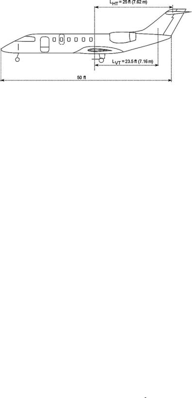
Figure 6.12. Civil aircraft example of empennage sizing
To maintain component commonality, the empennage is the same for all three variants. The baseline-designed empennage area is made sufficient for smaller aircraft; larger aircraft have a longer tail arm to enhance the empennage effectiveness.
So far, the civil aircraft design exercise provided the following data:
Estimated aircraft weight = 9,500 kg (at this stage, not required for empennage sizing)
Wing reference area = 30 m2 (low-wing design is popular and therefore chosen)
Wing MAC = 2.2 m (computed from Equation 3.21)
Fuselage length = 50 ft (aircraft length is different – see Figure 6.3)
To minimize the fuselage length, a T-tail configuration is chosen. The V-tail design arrangement is determined first to accommodate the position of the T-tail on top. Figure 6.12 illustrates the tail-arm lengths used to compute empennage areas.
Section 12.5 provides statistics for the V-tail volume coefficient, CVT, within the range 0.05 < CVT < 0.12. In the example, CVT = 0.07 is appropriate for the smaller aircraft variant. The V-tail quarter-chord sweepback is 15 deg in line with the wing sweep, to increase the tail arm LVT = 7.16 m (23.5 ft) measured from the aircraft CG to the V-tail MAC. In general, SVT/SW ≈ 0.12 to 0.2. The symmetrical aerofoil section is the NACA64–010. The V-tail height (semispan) = 7 ft (2.14 m) and the taper ratio = 0.6 to bear the load of a T-tail.
Equation 3.31 gives the V-tail reference area SVT = (CVT)(SW × wing span)/LVT. The V-tail is positioned on the fuselage end in consultation with structural engineers. Then, SVT = (0.07 × 30 × 15)/7.16 = 4.4 m2 (47.34 ft2). This would result in
sensible geometric details of the V-tail, as follows:
Note: Area, SV = 1/2 (CR + CT) × b or 4.4 = 0.5 × 1.6 CR × 2.14
Root Chord = 8.43 ft (2.57 m)
Tip Chord = 5.05 ft (1.54 m)
Aspect Ratio = 2.08
MAC = ( 32 × [(8.43 + 5.05) − (8.43 × 5.05)/(8.43 + 5.05] = 6.8 ft (2.07 m)
The V-tail area must be shared by the rudder and the fin. Typically, the rudder encompasses 15 to 20% of the V-tail area – in this case, it is 17%. This gives a rudder area of 0.75 m2 (8 ft2).
To check the CVT for the smaller variant, it should be more than 0.06. With one seat pitch plug removed from the aft fuselage, LVT short = 7.16 − 0.813 = 6.347 m

184 |
Configuring Aircraft |
(20.823 ft). This gives CVT short = (4.4 × 6.347)/(30 × 15) = 0.062 (sufficient for the shorter variant).
Section 12.5 provides the statistics of the H-tail volume coefficient, CHT, within the range 0.5 < CHT < 1.2. In this example, CHT = 0.7 is appropriate for the smaller aircraft variant. The H-tail is placed as a T-tail (dominant for smaller aircraft to increase the tail arm). The H-tail sweepback is 15 deg, in line with the wing sweep, and slightly more to increase the tail arm LVT = 7.62 m (25 ft) measured from the aircraft CG to the H-tail MAC. In general, SHT/SW ≈ 0.2 to 0.25. The aerofoil section is the NACA64–210 and the installation is inverted. The H-tail span equals 16.7 ft (5.1 m) and the taper ratio equals 0.5. Equation 3.30 gives the H-tail reference area, SHT = (CHT)(SW × MAC)/LHT.
The H-tail is positioned to give SHT = (0.7 × 30 × 2.132)/7.62 = 5.88 m2 (63.3 ft2), which is about 20% of the wing area. This area must be shared by the elevator and the stabilizer. Typically, the elevator uses 18 to 25% of the H-tail area; in this case, it is 20%, which results in an elevator area of 1.21 m2 (13 ft2).
This would result in sensible geometric details of the H-tail, as follows:
Note: Area, SH = 1/2 (CR + CT) × b or 5.88 = 0.5 × 1.5 CR × 5.1
Root Chord = 5.04 ft (1.54 m)
Tip Chord = 2.52 ft (0.77 m)
Aspect Ratio = 4.42
MAC = ( 32 ) × [(5.04 + 2.52) − (5.04 × 2.52)/(5.04 + 2.52)] = 3.9 ft (1.19 m)
To check the CHT for the smaller variant, it should be more than 0.6. With one seat pitch plug removed from the aft fuselage, LHT short = 7.62 − 0.813 = 6.807 m (22.33 ft). This gives CHT short = (6.063 × 6.807)/(30 × 2.2) = 0.625 (sufficient for the shorter variant).
6.7 Configuring a Civil Aircraft Nacelle: Positioning
and Layout of an Engine
The nacelle pod size depends on the choice of engine. At this design stage, a statistical value of uninstalled TSLS per engine is considered to determine the size of an engine. A formal engine sizing and matching is accomplished in Chapter 11. For better fuel economy, a large bypass ratio is desired. Dialogue with engine manufacturers (that can offer the class of engines) continues with “rubberized” engines (i.e., engines scalable and finely tuned to match the aircraft performance requirements for all variants). There are not many engine manufacturers from which to choose.
Numerous engine accessories (see Chapter 10) are part of the engine power plant. They are located externally around the casing of the engine (i.e., turbofan or turboprop). In general, these accessories are located below the engine; some are distributed at the sides (if the engine is underwing-mounted with less ground clearance). Therefore, the nacelle pods are not purely axi-symmetric and show faired bulges where the accessories are located.
Long-duct nacelles, chosen for the example, appear to be producing a higher thrust to offset the weight increase of the nacelle, while also addressing environmental issues of substantial noise reduction. Also, long-duct designs could prove more suitable to certain types of thrust reverser designs. This book only considers
6.7 Configuring a Civil Aircraft Nacelle: Positioning and Layout of an Engine |
185 |
long-duct design but it does not restrict the choice of short-duct nacelles.
For this example, the maximum nacelle diameter ≈ <1.5 × engine-face diameter (6.6)
In general, the intake length in front of the engine face ≈ <1.0 × engine-face diameter, and the exhaust jet-pipe length aft of the last stage turbine disc ≈ <1.5 × engine-face diameter.
The total nacelle length ≈ (engine length) + (k × engine-face diameter) (6.7)
where 1.5 < k < 2.5. For smaller engines, the value of k is lower.
For long-duct nacelles, the fineness ratio (i.e., length/maximum diameter) is between 2 and 3.
Pylons are the supporting structures (i.e., cross-section streamlined to the aerofoil shape) of the nacelle attaching to the aircraft and carrying all the linkages for engine operation. Aft-fuselage–mounted pylons are generally horizontal but can be inclined if the nacelle inlet must be raised. For wing-mounted nacelles, the pylon is invariably vertical. The depth of the pylon is about half of the engine-face diameter; the pylon length depends on the engine position. For an aft-fuselage–mounted installation, the pylon is nearly as long as the nacelle. For a wing-mounted installation, the nacelle is positioned ahead of the wing LE to minimize wing interference. In general, the t/c ratio of the pylon is between 8 and 10%.
The nacelle size is determined from the matched-engine dimensions. Using the considerations listed in Section 6.3.4, the following stepwise approach is suggested. The engine-thrust level indicates engine size (Figure 6.13). It is best to obtain the engine size from the manufacturer as a bought-out item.
Step 1: Configure the podded nacelle size.
The maximum engine diameter determines the maximum nacelle diameter. The ratio of the maximum nacelle diameter to the maximum engine diameter is given statistically in Chapter 10. Similarly, the length of the nacelle is established from the engine length. The keel cut is typically thicker than the crown cut to house accessories. In this book, the nacelle is symmetrical to the vertical plane but it is not a requirement.
Step 2: Position the nacelle relative to the fuselage.
The nacelle position depends on the aircraft size, wing position, and stability considerations (see Section 4.10). Subsequently, CFD analysis and wind-tunnel testing will fine-tune the nacelle size, shape, and position.
Step 3: Use pylons to attach the nacelle to the aircraft.
A worked-out example follows in the next section.
6.7.1 Worked-Out Example: Configuring and Positioning the Engine and Nacelle in Civil Aircraft
This section provides an example for configuring the nacelle based on an engine bought from an engine manufacturer. (Figure 4.9 gives the relationship between MTOM and engine thrust. Chapter 10 gives more details of engine dimensions).

186 |
Configuring Aircraft |
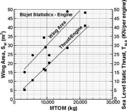
Figure 6.13. Statistics in the aircraft class: the uninstalled thrust of a turbofan
Unfortunately, Figure 4.8 is very coarse; however, Figure 6.13 provides similar information in finer detail confined to the aircraft class. The author recommends that readers produce graphs in higher resolution for the aircraft class under consideration. Unlike aircraft in general, the external dimensions of variant engines in a family do not change – the thrust variation is accomplished through internal changes of the engine (see Chapter 10). The same nacelle geometry can be used in all variants. For major variations, the engine size changes slightly, with minimal changes affecting the nacelle mould lines.
From the statistics in Figure 6.13, for a MTOM of 9,500 kg, a typical uninstalled engine thrust for this aircraft class indicates that TSLS/engine = 3,800 lb ± 25% for the derivative variants for the aircraft family to be offered. This may be considered a smaller engine. For better fuel economy, a larger BPR is desirable. Not many engines are available in this class. It is important that a proven, reliable engine from a reputable manufacturer be chosen; of interest are the following:
Honeywell (originally Garrett) TFE731 turbofan-series class.
Pratt and Whitney (Canada) PW 530 series class (not many variants available) (In the small engine class, Williams is coming up but is still below the required
size.)
The Rolls Royce Viper and the Turbomeca Larzac have a low BPR and are suited to a military application. This leaves the Honeywell TFE731–20 turbofan class as practically the only choice. It has a fan diameter of 0.716 m (28.2 inches), a bare engine length of 1.547 m (60.9 inches), and a dry weight of 379 kg (836 lb). At this stage, a generic long-duct nacelle pod to house is used (see Figure 6.13).
Using the relationship given in Equation 6.6, the maximum nacelle diameter = 1.5 × 0.716 = 1.074 m (5.52 ft).
Using the relation given in Equation 6.7, the nacelle length = 1.5 × 0.716 + 1.547 = 2.62 m (8.6 ft).
The nacelle fineness ratio = 2.62/1.074 = 2.44.
Being a small aircraft, the engines are aft-fuselage–mounted, one at each side. At this stage, a horizontal plate may represent the pylons that support the nacelles. The pylon length = 2.44 m (8 ft) with a thickness of 25 cm (9.8 in) and having a symmetrical cross-section aerofoil-like structure for ease of manufacture. Inlet and exhaust areas are established in Chapter 10.