

176 |
Configuring Aircraft |
Wing Reference Area
The wing reference area is obtained from the sizing of wing-loading W/S. At this stage, without knowing the aircraft weight, an initial estimate is derived from statistical values reflecting successful past designs. Subsequently, the wing will be sized to the requirement (see Chapter 1). Some iteration is required because component weights are revised at the stages of the study. In coursework activity, one iteration is sufficient.
Wing Sweep
Wing sweep, , is a function of aircraft speed to delay transonic effects. For aircraft flying at less than Mach 0.6, a wing sweep is not required. A tapered wing with a zero quarter-chord sweep has some LE sweep; the trailing-edge sweep depends on the taper ratio.
Wing Twist
It is an essential geometrical adjustment to ensure that wing-tip effects do not create adverse conditions. A major requirement is to make the wing root stall earlier to retain aileron effectiveness at a high angle of attack (low speed) – especially during landings. A wing twist with washout would favor such behavior (and is the prevailing practice).
Wing Dihedral/Anhedral
To ensure roll stability (see Section 12.3.3), wing dihedral and anehedral angles are used. Generally, the dihedral is associated with low-wing design and the anhedral with high-wing design; however, there are designs that are the reverse: a high wing can accommodate a dihedral. The type and extent are settled through stability analysis, which is not discussed in this book. All civil aircraft have some dihedral or anhedral angle between 1 and 5 deg. If a high wing and/or a high-wing sweep increases lateral stability more than what is required, the anhedral angle is required to reduce it to the desired level. Some low-wing Russian bombers have a high-wing sweep that necessitates an anhedral angle, when the undercarriage struts must be longer to provide the desired ground clearance.
6.5.3 Wing-Mounted Control-Surface Layout
Chapter 3 introduces a host of wing-mounted control surfaces (e.g., aileron, flap, slat, spoilers, and trim tabs), none of which are sized in this book; however, geometry from current designs is extracted and their placement should be earmarked. Control surface sizing is accomplished after the wing is sized and is addressed in subsequent design phases.
Flaps and slats are wing components that are selected for field-performance demands to generate high lift. In general, the more demanding aircraft-performance requirements, the more sophisticated are the high-lift devices, which are progressively more complex and therefore more expensive (see Section 3.12). Associated incremental lift gains by each type are shown in Figure 3.21. In general, a singleor double-slotted Fowler action flap suffices for the majority of civil transport aircraft. The simpler types are less costly to manufacture and are used in low-speed, low-cost smaller aircraft, usually compensated by the relatively larger wing area.
6.5 Configuring a Civil Aircraft Wing: Positioning and Layout |
177 |
The aileron span is about a third of the wing span at the extremities. Ailerons and flaps are hinged aft of the rear spar for up and down movements; provision for them should be made during the conceptual design phase. On some designs, flap tracks are used to support the flaps traveling outward to increase lift. A flaperon serves as both a flap and an aileron.
Flaps are positioned behind the wing rear spar (about 60 to 66% of the chord) and typically run straight or piecewise. Flaps take up about two thirds of the inner wing span. It is apparent that designers must have a good knowledge of the internal structural layout to configure an aircraft. Chapter 15 provides information on aircraft structure pertaining to the aircraft-configuration study.
Not all aircraft have wing spoilers; however, aircraft with speed over Mach 0.6 generally have spoilers. These are installed close to the aircraft CG line to minimize pitch change. Spoilers also act as air brakes. The differential use of spoilers is for lateral control and they are referred to as spoilerons. This book does not size spoilerons or air brakes but schematically earmarks their position on the wing.
6.5.4 Positioning of the Wing Relative to the Fuselage
Positioning of the wing relative to the fuselage is an iterative process dictated by the location of the aircraft CG at a desired position, expressed in terms of percentage of the wing MAC. The aircraft CG is kept close to the quarter-chord position of the wing MAC. Unfortunately, at this stage of design, the aircraft weight and CG are not accurately known.
A designer’s expertise is the way to estimate the wing position relative to the fuselage as a starting point. Experienced designers minimize the number of iterations that could occur with “wing-chasing,” explained in Section 4.11. The CG position varies with aircraft loading, fuel status, and military aircraft armament carried. Positioning of the wing should be such that the aircraft stability margin is not jeopardized by extremes of the operational CG position.
For newcomers to aircraft design, this offers an interesting exercise: Very quickly, a “feel” for locating the wing can be developed. A starting position for wing placement relative to the fuselage is approximately at the middle of the fuselage (somewhat farther behind for aft-mounted engines).
6.5.5 Worked-Out Example: Configuring the Wing in Civil Aircraft
Continuing with the fuselage-design example outlined in Section 6.4, following are specifications required for wing design:
Maximum Cruise Speed: Initial Cruise Altitude: Takeoff Field Length: Landing Distance from 50 ft:
Initial Rate of Climb:
Mach 0.74 (HSC)
Above 40,000 ft (ceiling more than 50,000 ft) 1,000 m at sea level (balanced field length) 1,000 m at maximum landing weight, as high as 0.95 MTOM at sea level
16 m/s
Unlike the fuselage, the approach to wing design starts with past statistics and is properly sized in Chapter 11. Following the considerations listed in Sections 6.3.2 and 6.5.2, a wing design could progress in a stepwise approach as suggested herein.
178 |
Configuring Aircraft |
(a) Wing |
(b) Empennage |
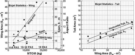
Figure 6.10. Statistics for the Bizjet class of aircraft
A worked-out example follows. Figure 6.10 is specifically for the aircraft class under consideration. Aircraft in the graphs are the Century, Cessna CJ2, Cessna Excel, Cessna 650, Lear 60, Cessna 750, and Challenger.
Step 1: Decide the aerofoil section.
This is one of the most important aspects of aircraft design. Aircraft performance depends considerably on the type of aerofoil adopted. Today, most designers in the major aircraft industry design their own aerofoil and keep the profile “commercial in confidence.” There are also many industries that use the established NACA-type aerofoil. This book uses the established aerofoil section available in the public domain. Aerodynamicists prefer the aerofoil to be as thin as possible, whereas structural engineers prefer it to be as thick as possible. A compromise is reached based on the aircraft design Mach number and the chosen wing sweep.
Step 2: Establish the wing reference area.
Initially, the wing reference area must be estimated from previous statistics. First, estimate the aircraft MTOW from the payload-range capability (see Figure 4.5). Next, estimate the wing reference area, SW, from the MTOW (see Figure 6.10a); this gives the wing-loading. Both the SW and the MTOW are accurately sized in Chapter 11. Position the wing relative to the fuselage, considering the aerodynamic and structural features.
Step 3: Establish the aspect ratio, wing sweep, taper ratio, dihedral, and twist (see Section 3.16).
The wing planform is generally of but not restricted to a trapezoidal shape – it can be modified with a glove and/or a yehudi. The choices for the wing-aspect ratio, wing sweep, and taper ratio are interlinked to keep the compressibility drag increase within twenty drag counts at the high-speed design specification (see Section 3.18). The aspect ratio should be the highest that the structural integrity will permit for the aerofoil t/c ratio and the wing root chord based on the taper
6.5 Configuring a Civil Aircraft Wing: Positioning and Layout |
179 |
||
|
ratio. At this stage, wing twist is empirically determined to improve |
|
|
|
stalling effects. The wing dihedral is decided from stability consider- |
|
|
|
ations. All these parameters are eventually fine tuned through CFD |
|
|
|
analysis and wind-tunnel testing, with the hope that flight-test results |
|
|
|
will not require further tweaking. |
|
|
Step 4: |
Establish the control surfaces (e.g., aileron and spoilers). |
|
|
|
Initially, these are approximated by reference to statistics and semi- |
|
|
|
empirical data; the sizing could be postponed until more details are |
|
|
|
available. In this book, the control surfaces are not sized. |
|
|
Step 5: |
Establish the high-lift devices (e.g., flap and slats). |
|
|
|
The first task is to decide the type of high-lift device required to |
|
|
|
meet the maximum CL to satisfy the specified field performance re- |
|
|
|
quirements (i.e., takeoff and landing). Once established, the area and |
|
|
|
other geometrical parameters are initially approximated by reference |
|
|
|
to the statistics and semi-empirical data. The sizing can be postponed |
|
|
|
until more details are available. In this book, the high-lift devices are |
|
|
|
not sized. |
|
|
To maintain component commonality, the wing should be the same for all three |
|
||
variants; obviously, it would be slightly larger for the smaller variant and slightly |
|
||
smaller for the larger variant. How this is determined satisfactorily is addressed in |
|
||
Chapter 11. |
|
|
|
Maintaining the established design trends, the planform shape of the example |
|
||
is taken as trapezoidal and assembled as a low wing to the aircraft. The aerofoil for |
|
||
the aircraft is a NACA 65–410 (i.e., 10% t/c ratio; see Appendix C). |
|
||
At this stage, the wing reference area and aircraft weight are not known. This is |
|
||
when the statistics of previous designs prove useful to initiate the starting point. |
|
||
Unfortunately, Figure 4.8 is very coarse; however, Figure 6.10 provides similar |
|
||
information in finer detail confined to the aircraft class. The author recommends |
|
||
that readers produce similar graphs in better resolution for the aircraft class under |
|
||
consideration. |
|
|
|
Figure 6.10a indicates a MTOM of approximately 9,000 to 10,000 kg, corre- |
|
||
sponding to 10 passengers. An average value of 9,500 kg (21,000 lb) is used for the |
|
||
example. The corresponding wing area is ≈30 m2 (322.9 ft2) of trapezoidal wing |
|
||
planform, which gives a wing-loading of 316.67 kg/m2 (65 lb/ft2). These are pre- |
|
||
liminary values and are formally sized in Chapter 11. However, the aspect ratio is |
|
||
reduced to 7.5 to keep the OEW light (it will be iterated). A taper ratio of 0.4 is |
|
||
used, which reduces the wing span. With a relatively low LRC Mach of 0.65, the |
|
||
compressibility effect is low and a quarter-chord sweep angle of 14 deg (see Figure |
|
||
3.36) would keep the wave drag to zero.√ |
√ |
|
|
The wing span is worked out as b = (AR × SW) = 225 = 15 m (49.2 ft). The |
|
||
wing root and tip chord (CR and CT) can now be worked out from the taper ratio |
|
||
of 0.4: |
|
|
|
CT/CR = 0.4 and SW = 30 = b × (CT + CR)/2, solving the equations |
|
||
|
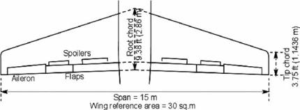
CR = 2.86 m (9.38 ft) |
and CT = 1.143 m (3.75 ft). |
|
Using Equation 3.21, the wing MAC = 32 |
× [2.87 + 1.148 – (2.87 × 1.148)/ |
|
|
(2.87 + 1.148)] = 2.132 m (7 ft). Figure 6.11 gives the wing plan form geometry. |
|
||
180 |
Configuring Aircraft |
Figure 6.11. Example of wing design
It is interesting that most typical values of taper, twist, and dihedral are derived from statistics and are about the same for the aircraft class. From the statistics, a twist of –2 deg (i.e., washout) and a dihedral of 3 deg are typical for the class. Eventually, CFD and wind-tunnel testing will fine-tune the values. A wing-loading of 316.67 kg/m2 (3,106.5 N/m2) is a moderate value that would provide good field performances. A single-slotted Fowler flap without a LE slat would be sufficient, saving considerably on costs.
Control areas are provisional and are sized in Phase 2. Initially, a company’s statistical data of previous experience serve as a good guideline. Aileron, flaps, and spoilers are placed behind the wing rear spar, which typically runs straight (or piecewise straight) at about 60 to 66% of the chord. With a simple trapezoidal wing planform, the rear spar runs straight, which keeps manufacturing costs low and the operation simpler; therefore, it has a lower maintenance cost. With a third of the wing span exposed, the aileron area per side is about 1 m2 (10.764 ft2). Similarly, the flap area is 2.2 m2 (23.68 ft2) per side. Subsequent performance analysis would ascertain whether these assumptions satisfy field-performance specifications. If not, further iterations with improved flap design are carried out.
From the test data, the following maximum lift coefficients are given:
Flap deflection – deg |
0 |
8 |
20 |
40 |
CLmax |
1.5 |
1.7 |
1.9 |
2.1 |
For a small aircraft with limited ground clearance, the engines would be mounted on the rear fuselage. At this stage, the wing is placed just behind the middle of the fuselage. The wing location is subsequently fine-tuned when the CG and undercarriage positions are known. A smaller aircraft wing could be manufactured in one piece and placed under the fuselage floorboards, minimizing a “pregnant-looking” fairing (Figure 3.35 shows a generous fairing to smooth the hump; however, the example in this book has more streamlined fairing).
6.6 Configuring a Civil Aircraft Empennage: Positioning and Layout
The function of the empennage is to provide a force/moment for stability and control. The fuselage length, wing reference area (SW), and tail arms LHT and LVT are the main parameters governing the empennage size. Semi-empirical relations given in the definition of tail volume coefficient (see Section 12.5) provide the statistical empennage size required (see Figure 12.11).