

6.3 Shaping and Layout of a Civil Aircraft Configuration |
155 |
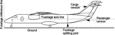
Figure 6.4. Fuselage upsweep angle
6.The minimum number of cabin crew depends on the maximum passenger capacity that the airframe can accommodate. Although not required for up to 19 passengers, a cabin crew is provided by some operators.
7.A pressurized fuselage is invariably circular or near circular to minimize weight. Unpressurized cabins for aircraft operating below 4,300 m (14,000 ft) need not be circular in the cross-section. Smaller utility aircraft demonstrate the benefits of a rectangular cross-section. A box-like rectangular cross-section (see Figure 4.14) would not only offer more leg space but also is considerably less costly to manufacture (e.g., the Short SD360).
8.The FAA and CAA have mandatory requirements on the minimum number of passenger doors, their types, and corresponding sizes dependent on the maximum passenger capacity for which the fuselage is intended to accommodate. This requirement ensures passenger safety: certification authorities stipulate a time limit (e.g., 90 s for big jets) within which all passengers must egress if an unlikely event occurs (e.g., fire). The larger the passenger capacity, the more doors are to be installed. Not all doors are the same size – emergency doors are smaller. Passenger doors have several categories and are described in Section 15.7. All doors are kept locked while airborne.
9.The fuselage provision typically includes a toilet, a galley, and cabin crew seating – the extent depends on the number of passengers and the duration of flight. Chapter 4 describes toilet and galley details. For smaller aircraft with a shorter duration of flight, it is desirable that at least a toilet be provided. To reduce cost, smaller aircraft with a low mission range do not have a toilet, but these aircraft can therefore be uncomfortable.
Closure of the Fuselage
When the seating arrangement is determined in the midfuselage section, it must be closed at the front and aft ends for a streamlined shape, maintaining a fineness ratio from 7 to 14 (see Table 4.3). Typical frontand aft-fuselage closure ratios are in Table 4.4.
The fuselage upsweep angle of the aft-end closure depends on the type of aircraft. If it has a rear-loading ramp as in a cargo version, then the upsweep angle is higher, as shown in Figure 6.4. The fuselage clearance angle, θ , depends on the main-wheel position of the undercarriage relative to the aircraft CG position (see
156 |
Configuring Aircraft |
Chapter 7). The typical angle for θ is between 12 and 16 deg to approach CLmax at aircraft rotation.
The next step is to construct a fuselage axis and set the zero reference plane normal to the fuselage axis, as explained in Section 3.23. In Figure 6.4, the fuselage axis is shown passing through the tip of the nose cone, where the zero reference plane starts. In this book, the zero reference plane is at the nose of the aircraft (it could be ahead of the nose cone tip). The zero reference plane and the fuselage axis are data for measuring relative distances of various aircraft components and for aerodynamic geometries for use in calculations.
The fuselage axis is an arbitrary line but it must be in the plane of aircraft symmetry. In general, for aircraft with a constant fuselage section, the fuselage axis is placed conveniently in the middle of the aircraft. The fuselage axis line could be the fuselage centerline. It is easier to assess if the reference lines are vertical and horizontal. If the aircraft’s normal position on the ground does not render the aircraft centerline horizontal, then the ground is tilted to show it with the associated angle. For simplification, this book keeps the centerline and ground horizontal, as shown in Figure 6.4. For military and smaller civil aircraft, there is no constant fuselage section, and the aircraft centerline must be conveniently chosen; it is the designer’s choice as long as the reference lines are clearly defined and adhered to for the entire life cycle of an aircraft that could encounter design modifications in its service life. The other possible choice is the fuselage axis as the principal inertia axis.
An interesting concept is to make variants of a modular fuselage – that is, with two types of aft ends easily interchangeable (see Figure 6.4). One type is for the conventional passenger version with a pointed aft-end closure, the other is for the cargo version with an increased upsweep to accommodate a rear-loading ramp. It can even be a “quick-change” version, swapping the type of fuselage needed for the mission; the changeover joint is located behind the main undercarriage.
Attaching the wing to the fuselage could have a local effect on the fuselage external shape. Following are the basic types of attachments:
1.Carry-through wing box. For larger aircraft, this is separately constructed and attached to the fuselage recess. Subsequently, wings are mated at each side in accurate assembly jigs. For smaller aircraft, it could be integral to the wing and then attached to the fuselage recess. In that case, the wing box is built into the wing, either in two halves or as a tip-to-tip assembly. A fairing at the junction reduces the interference drag. These wing boxes are primarily suited to civil aircraft designs. A central wing box is a part of the wing structure that integrates with the fuselage and is positioned high, low, or at a convenient mid-location (see Section 3.16).
2.Central beam and root attachments. These have a simpler construction and therefore are less costly, suited to smaller aircraft.
3.Wing roots (with multispar) joined to a series of fuselage frames. These are mostly suited to military aircraft designs. They are heavier and can be tailored to varying fuselage contours. The wing root is then secured to the fuselage structure, sometimes outside the shell, with attachments.
4.Strut/braced wing support. This is suited to smaller, low-speed, high-wing aircraft. Some low-wing agricultural aircraft have braced wings. Struts add to drag
6.3 Shaping and Layout of a Civil Aircraft Configuration |
157 |
but for a low-speed operation, the increment can be tolerated when it is less costly to build and lighter in construction.
5.Swing wing. Attachment of a swing wing is conveniently outside the fuselage such that the pivots have space around them to allow wing rotation.
For smaller aircraft, the wing must not pass through the fuselage interior, which would obstruct passenger movement. If the wing is placed outside the fuselage (i.e., top or bottom), then a large streamlined fairing on the fuselage would accommodate the wing box. The example of the Cessna Excel shows a low-wing design; the DO328 includes a fairing for the high-wing design. The Dornier 328 (see Figure 3.33) conceals the fairing that merges with the fuselage mould lines. The extra volume could be beneficial; however, to arrive at such a configuration, a proper DOC analysis must demonstrate its merits. High-wing aircraft must house the undercarriage in a fuselage fairing, although some turboprop aircraft have the undercarriage tucked inside the engine nacelles positioned below the wing (see Figure 10.19).
6.3.2 Considerations in Configuring the Wing
Following are general considerations important for designing the wing:
Geometry |
Aerodynamics |
||
(1) |
wing reference area, SW |
(1) |
drag |
(2) |
span and aspect ratio |
(2) |
lift and moment |
(3) |
aerofoil section, t/c ratio |
(3) |
stall, critical Mach |
(4) |
sweep, twist, dihedral, taper |
(4) |
high-lift devices |
(5) |
position (for the CG) |
(5) |
control surfaces |
(6) |
glove/yehudi, if any |
(6) |
wing/tail position |
Structure (affecting weight |
|
|
|
and external geometry) |
Systems |
||
(1) |
spar and rib positions |
(1) |
control linkage |
(2) |
stiffness, aeroelasticity, and |
(2) |
fuel system |
|
torsion stability |
(3) |
electrical |
(3) |
fuel volume |
(4) |
anti-icing |
(4)undercarriage and nacelle, if any
(5)weight
The first task for wing design is to select a suitable aerofoil. This book does not undertake aerofoil design; rather, it uses established 2D aerofoil data from the public domain (the aerofoil data in Appendix C are sufficient for this book). Industry takes an arduous route to extract as much benefit from its in-house research that is kept commercial in confidence. It is an established technology in which there is a diminishing return on investment. However, the differences between the best designs and those in the public domain are enough to encourage industrial competition. The next task is to configure a wing planform with a reference area typically for the class of aircraft. It is not determined by the passenger number as in the fuselage; the initial wing size is determined from statistics. Subsequently, the prelimi- nary wing reference area must be sized using the methodology described in Chapter 11.
158 |
Configuring Aircraft |
Positioning of the wing relative to the fuselage is an important part of configuring an aircraft. It requires knowledge of the CG position and its range of movement with weight variation (i.e., fuel and payload). Because the aircraft weight distribution is not yet established, it is initially estimated based on experience and past statistics in the aircraft class. If nothing is known, then a designer may position the wing just behind the middle of the fuselage for rear-mounted engines or at the middle of the fuselage for wing-mounted engines. Subsequently, the wing position must be iterated after the aircraft component weights are known and the wing is sized. This may not be easy because moving the wing will alter the CG position – an inexperienced engineer could encounter what is called “wing chasing”; however, this is not a major concern. Here, the “zero reference plane” (typically at the nose of the fuselage) assists in tracking the aircraft-component positions.
A generous wing root fairing is used to reduce interference drag as well as vortex intensity at the aft-fuselage flow. A large aircraft BWB is an extreme example that eliminates wing root fairing problems. There is no analytical expression to specify the fairing curvature – a designer should judge the geometry from past experience and CFD analysis, considering the internal structural layout and the associated weight growth. In principle, a trade-off study between weight growth and drag reduction is needed to establish the fairing curvature. At this stage, visual approximation from past experience is sufficient: Observe the current designs and make decisions.
6.3.3 Considerations in Configuring the Empennage
Following are general considerations important for configuring the empennage (see also Section 6.6):
Geometry |
Aerodynamics |
||
(1) |
H-tail and V-tail reference |
(1) |
drag, lift, moment |
|
area, SH and SV |
(2) |
tail volume coefficient |
(2) |
span and aspect ratio |
(3) |
stall and yaw recovery |
(3) |
aerofoil section, t/c ratio |
(4) |
control and trim surfaces |
(4) |
sweep, twist, or dihedral, |
(5) |
spin recovery |
|
whichever is applicable |
(6) |
balancing |
(5) |
position relative to wing (tail |
(7) |
engine-out cases |
|
arm) |
|
|
(6)position H-tail to
avoid shielding of V-tail
(7)H-tail position (high α clearance, T-tail)
Structure (affecting weight |
|
|
|
and external geometry) |
Systems |
||
(1) |
spar and rib positions |
(1) |
control linkage |
(2) |
stiffness, aeroelasticity, and |
(2) |
control actuation |
|
torsion stability |
(3) |
electrical (if any) |
(3)fuel volume (if any)
(4)weight
6.3 Shaping and Layout of a Civil Aircraft Configuration |
159 |
The descriptions and definitions of the empennage are in Sections 3.22 and 4.9. The dominant civil aircraft empennage consists of the H-tail and V-tail placed symmetrically about the fuselage axis. The H-tail could be positioned anywhere (see Figure 4.24), going through the aft fuselage to the tip of the V-tail forming a T-tail. Some aircraft have twin booms, where the empennage has the same function; the V-tail is split over two booms.
It is important that the V-tail remains effective for the full flight envelope. Shielding of the V-tail, especially the control areas, may prove to be dangerous. A designer must ensure that the V-tail keeps at least 50% of the rudder unshielded (see Figure 4.26) at a high angle of attack. (The canard configuration is not worked out in this book). Also, at a high angle of attack, the H-tail should not remain within the wing wake; otherwise, it must be enlarged to be effective.
If a FBW control system is incorporated, the empennage sizes can be reduced because the aircraft would be able to fly safely under relaxed stabilities. However, this book is not concerned with control laws as design input in an introductory course. The FBW concept is introduced in Chapter 12 but not analyzed. It will not be long until tailless aircraft such as the B2 bomber appear in civil aircraft designs, especially for BWB aircraft.
6.3.4 Considerations in Configuring the Nacelle
Following are general considerations important for configuring the nacelle (see also Section 6.7):
Geometry
(1)diameter (comfort level, appeal)
(2)length, fineness ratio
(3)wing and fuselage position and pylon geometry
(4)ground clearance
(5)cross-section to house accessories
(6)intake geometry and lip section
Structure (affecting weight and external geometry)
(1)engine burst considerations
(2)foreign-object ingestion problems
(3)fuel volume
(4)weight
(5)nose gear collapse
(6)access
Aerodynamics
(1)drag
(2)interference
(3)surface roughness
(4)noise/emission
(5)vibration
(6)thrust and bypass ratio (BPR) level
Systems
(1)control linkage
(2)fuel system
(3)electrical
(4)thrust reverser
(5)fire prevention
(6)anti-icing
Civil aircraft designs are invariably externally pod-mounted on either the wing or the aft fuselage (smaller low-wing turbofan engines). The demonstration of high engine reliability enables an ETOPS clearance by the FAA for a two-engine