

150 |
Configuring Aircraft |
coursework, one iteration is sufficient. An experienced chief designer could start with a preliminary configuration that is close to the final arrangement.
There is no mathematics in this chapter; rather, past designs and their reasoning are important in configuring a new aircraft. Readers need to review Sections 4.11, 12.8, 12.9, and 13.7 on design considerations and discussion to gain insight from experience. Statistics is a powerful tool that should be used discriminately. Researchers and academics have worked on statistics to a great extent; however, in many cases, current market demands have stabilized statistics (Section 6.4).
6.1.1 What Is to Be Learned?
This chapter covers the following topics:
Section 6.2: Introduction to configuring aircraft geometry: shaping and layout
Section 6.3: Shaping and layout of civil aircraft
Section 6.4: Civil aircraft fuselage shaping and layout with example Section 6.5: Configuration of civil aircraft wing design with example Section 6.6: Configuration of civil aircraft empennage design with example Section 6.7: Configuration of civil aircraft nacelle design with example Section 6.8: Undercarriage design considerations
Section 6.9: Finalizing civil aircraft configuration
Section 6.10: Miscellaneous considerations for civil aircraft Section 6.11: Shaping and layout of military aircraft
Section 6.12: Configuration of military advanced jet trainer with example Section 6.13: Configuration of military aircraft CAS version with example
6.1.2 Coursework Content
Intensive classroom work starts with this chapter, one of the most important in the book. Readers begin with the layout of aircraft geometry derived from customer specifications. The information in Chapters 3 and 4 is used extensively to configure the aircraft.
6.2 Introduction
Section 2.6 stressed that the survival of the industry depends on finding a new and profitable product line with a competitive edge. A market study is the tool to establish a product by addressing the fundamental questions of why, what, and how. It is like “crystal-ball gazing” to ascertain the feasibility of a (ad)venture, to assess whether the manufacturer is capable of producing such a product line.
Ideally, if cost were not an issue, an optimum design for each customer might be desirable, but that is not commercially viable. Readers can begin to appreciate the drivers of commercial aircraft designs: primarily, economic viability.
The product line should be offered in a family of variants to encompass a wide market area, at lower unit cost, by maintaining component commonalities. The first few baseline aircraft are seen as preproduction aircraft, which are flight-tested and subsequently sold to operators.
6.2 Introduction |
151 |
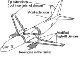
Typical modifications for derivative in the family
Possible changes (shaded area) in civil aircraft family derivatives (B737)
Figure 6.1. Variants in the Boeing 737 family
The final configuration is a “satisfying” design, which implies that the family of variants is best suited to satisfy as many customers as possible. Figure 6.1 shows how variants of the Boeing 737 family have evolved. Here, many of the fuselage, wing, and empennage components are retained for both the variants.
However, military aircraft designs are dictated by national requirements when superiority, safety, and survivability are dominant, of course, but without ignoring economic constraints. Today’s military aircraft designs start with technology demonstrators to prove the advanced concepts, which are considered prototype aircraft. Production versions could be larger, incorporating the lessons learned from the demonstrator aircraft.
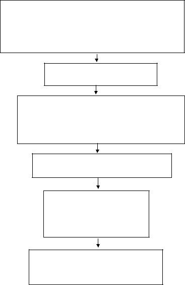
Finalizing the aircraft configuration as a marketable product follows a formal methodology, as outlined in Chart 6.1; it is an iterative process.
Chapter 2 presents several aircraft specifications and performance requirements of civil and military aircraft classes. From these examples, the Learjet 45 class and RAF Hawk class – one each in the civil and the military categories, respectively – are worked out as coursework examples. These examples of civil aircraft family derivatives are shown in Figure 6.8; the baseline aircraft is in the middle of the figure and shown in Figure 6.2.
Initially, the conceptual study proposes several candidate aircraft configurations to search for the best choice. Comparative studies are carried out to confirm which choice provides the best economic gains. Although in practice there are potentially several candidate configurations for a specification, only one is addressed. Figure 6.3 shows four possible configurations (i.e., author-generated for coursework only). Comparative studies must follow in order to select one. The first configuration offers the best market potential (Figure 6.2).
Today, the industry uses CAD-generated aircraft configurations as an integral part of the conceptual design process, which must be implemented in classwork as soon in the process as possible. Most universities have introduced CAD training early enough so that students become proficient. If the use of CAD is not feasible, then accurate manual drawings are required; it is imperative that practitioners maintain accuracy and control of manual drawings. CAD enables changes in drawings to be made easily and quickly; in manual drawings, the new shape may necessitate a total redraw.
152 |
Configuring Aircraft |
Step 1 (Chapter 6)
Configure civil aircraft to a preliminary layout from market specifications:
1.First, size fuselage from passenger capacity.
2.Guess the MTOM from payload-range – use statistics of past designs.
3.Guess the wing area from the MTOM – use statistics of past designs.
4.Place wing relative to fuselage; past experience.
5.Position empennage and size it relative to wing area and fuselage tail arms.
6.Select engine from what is available in market and size thrust from statistics.
Step 2 (Chapter 7)
Position undercarriage and check out aircraft rotation and turning onground.
Step 3 (Chapter 8)
1. Make weight estimate from the preliminary configuration.
2. Revise the guessed MTOM of Step 1 with the updated estimated MTOM (iterate).
3.Place the CG in the appropriate place.
4.Reposition wing and undercarriage with respect to aircraft, as necessary.
5.Resize empennage (iterate).
Step 4 (Chapter 9)
Estimate aircraft drag (takeoff and cruise) of the preliminary aircraft configuration obtained in Step 3.
Step 5 (Chapters 10 & 11 Formally size aircraft with matched engine to
meet aircraft performance specifications. The revised aircraft size must be iterated through Chapters 7 to 9
(one iteration in course)
Step 6 (Chapters 11, 12, and 13)
1. Check staticstability. Generate matched engine performance and estimate aircraft performance.
2.If not achieved, make changes where the shortfall appears.
3.Finalize the configuration when satisfied.
Chart 6.1. Phase I, conceptual study: methodology for finalizing civil aircraft configurations
A three-view diagram should show the conceptualized aircraft configuration. A preliminary configuration will change when it is sized; for experienced engineers, the change is relatively minor. Having CAD 3D parametric modeling allows changes to be easily, quickly, and accurately incorporated. Making 2D drawings (i.e., threeview) from 3D models is simple with a few keystrokes.
6.3 Shaping and Layout of a Civil Aircraft Configuration
The objective is to generate aircraft components, piece by piece in building-block fashion, and mate them as shown in the middle diagram of Figure 2.3. Section 4.11 summarizes civil aircraft design methodology.

6.3 Shaping and Layout of a Civil Aircraft Configuration |
153 |
Figure 6.2. Four candidate aircraft configurations
Subsequently, in the next level, a more detailed breakdown (see first diagram in Figure 2.3) of the aircraft components in subassembly groups provides a better understanding of the preliminary layout of the internal structures and facilitates preliminary cost estimates. DFM/A consideration for subassembly components design is important in reducing production cost because the aircraft cost contributes significantly to the DOC (see Chapter 16).
The general methodology is to start with the fuselage layout, which is determined from the payload requirement (i.e., passenger capacity, number of seats abreast, and number of rows). The aerodynamic consideration is primarily deciding the front and aft closure shape for civil aircraft designs. The following section describes seating-layout schemes for 2- to 10-abreast arrangements encompassing passenger capacity from 4 to more than 600.
The next step is choosing a wing planform and an aerofoil section suitable for the desired aircraft performance characteristics. Initially, the wing reference area is estimated from statistics and is sized later in the process. The next step is to
Figure 6.3. The baseline version of the family concept of the classwork example
154 |
Configuring Aircraft |
configure the empennage based on the current wing area. It will be resized (i.e., iteration) when the wing area is more accurately sized. Initially, the location of the wing relative to the fuselage and empennage is based on past experience and finetuned iteratively after establishing the aircraft CG and wing geometry. Finally, a matched engine is selected from what is available in the market. Engine matching is worked out simultaneously with wing sizing (see Chapter 11).
6.3.1 Considerations in Configuring the Fuselage
Following are general considerations important for the fuselage layout. Section 3.23 provides definitions of associated fuselage geometries.
Geometry |
Aerodynamics |
||
(1) |
diameter (e.g., comfort |
(1) |
front-end closure |
|
level, appeal) |
(2) |
aft-end closure |
(2) |
abreast seating |
(3) |
surface roughness |
(3) |
length, fineness ratio |
(4) |
wing–body fairing |
(4) |
upsweep for rotation angle |
(5) |
wing and tail position |
|
and rear door, if any |
(6) |
drag |
(5)cross-section to suit under floorboards and headroom volume and space
Structure (affecting weight |
|
|
|
and external geometry) |
Systems |
||
(1) |
doors and windows |
(1) |
flight deck design |
(2) |
wing and undercarriage |
(2) |
passenger facilities |
|
attachments |
(3) |
all other systems |
(3) |
weight |
|
|
Section 6.4 describes typical fuselage layouts from two-abreast seating to the current widest seating of ten abreast.
The important considerations for civil aircraft fuselage layout are as follow:
1.The current ICAO limit on fuselage length is 80 m. This is an artificial limit based on current airport infrastructure size and handling limitations.
2.The fuselage fineness ratio must be from 7 to 14 (see Table 4.3). Section 4.7.3 lists frontand aft-fuselage closure shapes. Section 6.3.1.2 describes how to make the fuselage closure. There is aft luggage space in front of the pressure bulkhead, especially in smaller aircraft.
3.Seat and aisle dimensions are obtained from Table 4.5.
4.For a fuselage with four-abreast seating or more, the cross-section could use space below the floorboards. If the bottom half is elongated (i.e., oval), then the space can be maximized. Full standing headroom is easily achievable for a fuselage with four-abreast seating or more. Cargo container sizes are described in Section 4.7.8.
5.Two aisles are provided for a fuselage with seven-abreast seating and more (the current maximum is ten). In the future, if a wider cabin is designed (e.g., with a BWB), then more than two aisles will be necessary.