

3.17 Mean Aerodynamic Chord |
79 |
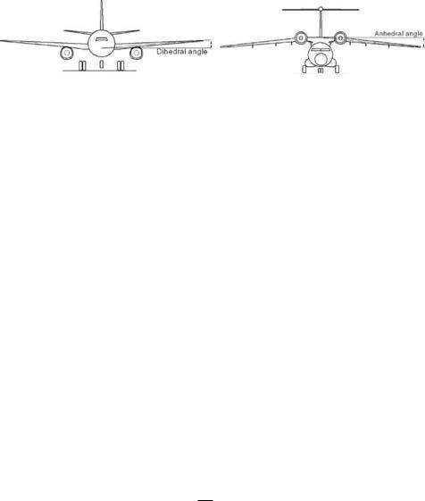
(a) Dihedral (midwing – low tail) |
(b) Anhedral (high-wing – T-tail) |
Figure 3.34. Wing dihedral and anhedral angles
main-undercarriage wheel track (see Chapter 7), allowing better ground maneuvering. A low wing also offers a better crashworthy safety feature in the extremely rare emergency situation of a belly landing. However, the author believes more high-winged, large commercial transport aircraft could be developed. Design trends shows that military transport aircraft have predominantly high wings with large rearmounted cargo doors.
3.16.8 Dihedral/Anhedral Angles
Aircraft in a yaw/roll motion have a cross-flow over the wing affecting the aircraft roll stability (see Chapter 12). The dihedral angle (i.e., the wing tip chord raised above the wing root chord) assists roll stability. A typical dihedral angle is between 2 and 3 deg and rarely exceeds 5 deg. Figure 3.34a shows that the dihedral angle with a low-wing configuration also permits more ground clearance for the wing tip. The opposite of a dihedral angle is an anhedral angle, which lowers the wing tip with respect to the wing root and is typically associated with high-wing aircraft (Figure 3.34b). The dihedral or anhedral angle also can be applied to the horizontal tail.
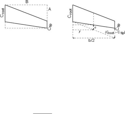
3.17 Mean Aerodynamic Chord
Various wing reference geometries and parameters are used in aerodynamic computations. A most important parameter is the mean aerodynamic chord (MAC), which is the chord-weighted average chord length of the wing, defined as follows:
|
2 |
0 |
b/2 |
|
|
MAC = |
c2dy, |
(3.37) |
|||
SW |
where c is the local wing chord and SW is the wing reference area:
trapezoidal wing reference area, SW (with sweep) (Figure 3.35) half wing area = rectangle – two triangles
=A × B − 1/2(A − CR) × B − 1/2(A − CT) × B
=A × B − 1/2(A × B) + 1/2(B × CR) − 1/2(A × B) + 1/2(B × CT)
=1/2(CR + CT) × B
For the full wing when the span b = 2B:
1 |
(CR + CT) × b |
wing area, SW = /2 |
Evaluating Equation 3.20 for the linear trapezoidal wing results in:
c = Croot − 2(Croot − Ctip)y/b
80 |
Aerodynamic Considerations |
Figure 3.35. Trapezoidal wing planform – MAC
When substituting the integral, Equation 3.37 becomes:
|
2 |
|
|
b/2 |
|
C |
b/2 |
|
y3 |
b/2 |
|
|
MAC = |
|
|
CR2 |
0 |
− |
4 R |
(CR − CT) 0 |
− 4(CR − CT)2 |
|
0 |
||
|
SW |
b |
3b2 |
|||||||||
= |
(2/SW)[bCr2/2 − bCR(CR − CT)/2 − b(CR − CT)2/6] |
|
|
|
||||||||
When substituting for the SW:
MAC = [2/(CR + CT)] C2r − C2r + CrCT + C2r /3 + C2T/3 − 2CrCT/3 = [2/(CR + CT)] C2r /3 + C2T/3 − CrCT/3
|
2 |
|
(CR |
CT)2 |
|
CRCT |
|
||
= |
|
|
+ |
CT) |
− |
|
|
|
|
3 |
(CR |
(CR |
+ |
CT) |
|||||
|
|
|
+ |
|
|
|
|
|
|
For a linearly tapered (trapezoidal) wing, this integral is equal to:
MAC = 2/3[Croot + Ctip − CrootCtip/(Croot + Ctip)] |
(3.38) |
For wings with a glove/yehudi, the MAC may be computed by evaluating each linearly tapered portion and then taking an average, weighted by the area of each portion. In many cases, however, the MAC of the reference trapezoidal wing is used. The MAC is often used in the nondimensionalization of pitching moments as well as to compute the reference length for calculating the Re as part of the wing drag estimation. The MAC is preferred for computation over the simpler mean geometric chord for aerodynamic quantities whose values are weighted more by the local chord, which are reflected by their contribution to the area.
3.18 Compressibility Effect: Wing Sweep
Section 3.7.1 explains the transonic effect resulting from the thickness distribution along an aircraft body. On the wing, the same phenomenon can occur, most importantly along the wing chord but altered due to the 3D wing tip influence. A local shock interacting with the boundary layer can trigger early separation, resulting in unsteady vibration and – in extreme cases – even causing the wing to stall. A typical consequence is a rapid drag increase due to the compressibility effect resulting from the transonic-flow regime. Military aircraft in hard maneuver can enter into such an undesirable situation even at a lower speed. As much as possible, designers try to
3.18 Compressibility Effect: Wing Sweep |
81 |
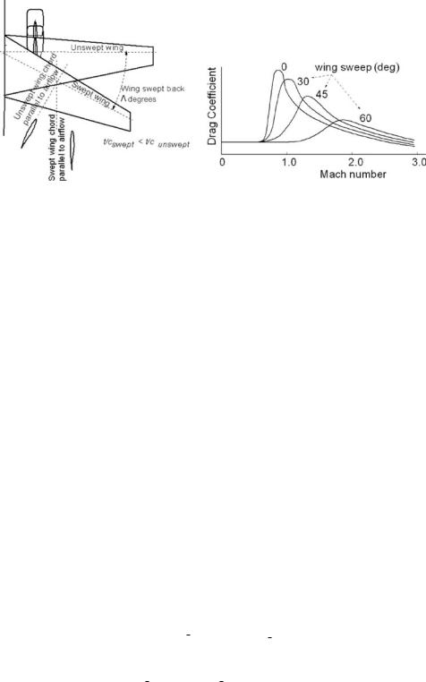
(a) Sweep definition |
(b) Drag comparison |
Figure 3.36. Sweep of wing
avoid, delay, or minimize the onset of flow separation over the wing due to local shocks.
Drag divergence is a sudden increase in drag. A 20-count drag rise (CD = 0.002) at the Mach number is known as the drag divergence mach (MDD), shown in Figure 3.36b. The critical Mach (Mcrit) is the onset of the transonic-flow field and is lower than the MDD. Some texts use Mcrit with a 20-count drag increase.
Structural engineers prefer aerofoil sections to be as thick as possible, which favors structural integrity at lower weights and allows the storage of more fuel onboard. However, aerodynamicists prefer the aerofoil to be as thin as possible to minimize the transonic-flow regime in order to keep the wave drag rise lower. One way to delay the Mcrit is to sweep the wing (Figure 3.36a) either backward (see Figure 3.31, Boeing 737) or forward (see Figure 4.37e, SU47 [at www.cambridge
.org/Kundu]), which thins the aerofoil t/c ratio and delays the sudden drag rise (Figure 3.36b). The former is by far more prevalent because of structural considerations. Wing slide (i.e., in which the chord length remains the same) is different from wing sweep, in which the chord length is longer by the secant of the sweep angle.
Shown here is the relationship between the sweep angle and wing geometries. The chord length of a swept wing increases, resulting in a decrease in the t/c ratio:
chordswept = (chordunswept)/Cos |
(3.39) |
This results in: |
|
(thickness/chordswept) < (thickness/chordunswept) |
(3.40) |
This directly benefits the drag divergence Mach number, divided by the cosine of the sweep angle:
1/4; that is, Machdiv swept = Machdiv unswept/Cos 1/4 |
(3.41) |
The sweep also degrades the CLmax by the cosine of the sweep angle, 1/4; that is:
CLmax swept = CLmax unswept × Cos 1/4 |
(3.42) |
If the trailing edge can remain unswept, then flap effectiveness is less degraded due to a quarter-chord sweep.
82 |
Aerodynamic Considerations |
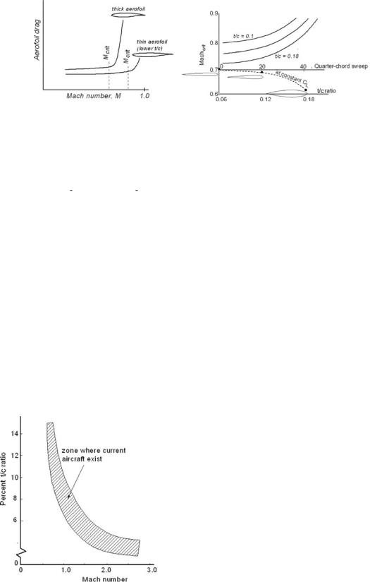
Figure 3.37. Wing sweep versus aerofoil t/c ratio
Qualitative characteristics between the wing sweep and the t/c ratio variation are shown in Figure 3.37.
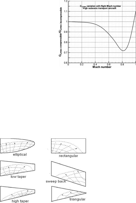
Figure 3.38 shows typical values used in various aircraft. Another effect of speed gain is a change in CLmax, as shown in Figure 3.39. For a particular wing, the ratio of CLmax compressible/CLmax incompressible decreases to approximately 0.7, as shown in Figure 3.39.
Designers require this body of information for the aerofoil selection. The choice decides the extent of wing sweep required to lower the t/c ratio to achieve the desired result (i.e., to minimize the compressible drag increase for the cruise Mach number) while also satisfying the structural requirements. To standardize drag-rise characteristics, the flow behavior is considered to be nearly incompressible up to Mcrit and can tolerate up to MDD, allowing a 20-count drag increase ( CD = 0.002).
3.19 Wing Stall Pattern and Wing Twist
The lower the speed at landing, the safer is the aircraft in case of any inadvertent mishap. An aircraft landing occurs near the wing stall condition when the aileron effectiveness should be retained to avoid a wing tip hitting the ground. In other words, when approaching the stall condition, its gradual development should start from the wing root, which allows the aileron at the wing tip to retain its ability to maintain level flight. Figure 3.40 (see also Figure 3.18) shows typical wing stall propagation patterns on various types of wing planforms.
Figure 3.38. Thickness-to-chord ratio for various aircraft
3.20 Influence of Wing Area and Span on Aerodynamics |
83 |
Figure 3.39. Mach number effect
Because a swept-back wing tends to stall at the tip first, twisting of the wing tip nose downward (i.e., washout) is necessary to force the root section to stall first, thereby retaining roll control during the landing.
A good way to ensure the delay of the wing tip stall is to twist the wing about the Y-axis so that the tip LE is lower than the wing root LE (see Figure 3.32). Typical twist-angle values are 1 to 2 deg and rarely exceed 3 deg.
3.20 Influence of Wing Area and Span on Aerodynamics
For a given wing loading (i.e., the wing area and maximum takeoff mass [MTOM] invariant), aerodynamicists prefer a large wingspan to improve the aspect ratio in order to reduce induced drag at the cost of a large wing root bending moment. Structural engineers prefer to see a lower span resulting in a lower aspect ratio.
Stall progressing from trailing edge as angle of attack is increased
Figure 3.40. Wing stall patterns