

3.7 Aerofoil |
59 |
Aerofoil pressure distribution is measured in a wind tunnel to establish its characteristics, as shown in [4]. Wind-tunnel tests are conducted at midspan of the wing model so that results are as close as possible to 2D characteristics. These tests are conducted at several Re. Higher Re indicates higher velocity; that is, it has more kinetic energy to overcome the skin friction on the surface, thereby increasing the pressure difference between the upper and lower surfaces and, hence, more lift.
In earlier days, drawing the full-scale aerofoils of a large wing and their manufacture was not easy and great effort was required to maintain accuracy to an acceptable level; their manufacture was not easy. Today, CAD/CAM and microprocessorbased numerically controlled lofters have made things simple and very accurate. In December 1996, NASA published a report outlining the theory behind the U.S. National Advisory Committee for Aeronautics (NACA) (predecessor of the present-day NASA) airfoil sections and computer programs to generate NACA aerofoils.
3.7.1 Groupings of Aerofoils and Their Properties
From the early days, European countries and the United States undertook intensive research to generate better aerofoils to advance aircraft performance. By the 1920s, a wide variety of aerofoils appeared and consolidation was needed. Since the 1930s, NACA generated families of aerofoils benefiting from what was available in the market and beyond. It presented the aerofoil geometries and test results in a systematic manner, grouping them into family series. The generic pattern of the NACA aerofoil family is listed in [4] with well-calibrated wind-tunnel results. The book was published in 1949 and has served aircraft designers (civil and military) for more than a half-century and is still useful. Since its publication, research to generate better aerofoils for specific purposes continued, but they are made in the industry and are “commercial in confidence.”
Designations of the NACA series of aerofoils are as follows: the four-digit, the five-digit, and the six-digit, given herein. These suffice for the purposes of this book – many fine aircraft have used the NACA series of aerofoils. However, brief comments on other types of aerofoils are also included. The NACA fourand five-digit aerofoils were created by superimposing a simple camber-line shape with a thickness distribution that was obtained by fitting with the following polynomial [4]:
y = ± (t/0.2) × (0.2969 × x0.5 − 0.126 × x − 0.3537 × x2 + 0.2843 |
|
× x3 − 0.1015 × x4) |
(3.20) |
NACA Four-Digit Aerofoil
Each of the four digits of the nomenclature represents a geometrical property, as explained here using the example of the NACA 2315 aerofoil:
2 |
3 |
Maximum camber |
Maximum thickness of |
position in % chord |
maximum camber in 1/10 |
|
of chord |
15
The last two digits are maximum t/c ratio in % of chord
60 |
Aerodynamic Considerations |
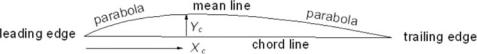
Figure 3.11. Camber line distribution
The camber line of four-digit aerofoil sections is defined by a parabola from the LE to the position of maximum camber followed by another parabola to the trailing edge (Figure 3.11). This constraint did not allow the aerofoil design to be adaptive. For example, it prevented the generation of an aerofoil with more curvature toward the LE in order to provide better pressure distribution.
NACA Five-Digit Aerofoil
After the four-digit sections came the five-digit sections. The first two and the last two digits represent the same definitions as in the four-digit NACA aerofoil. The middle digit represents the aft position of the mean line, resulting in the change in the defining camber line curvature. The middle digit has only two options: 0 for a straight and 1 for an inverted cube. The NACA five-digit aerofoil has more curvature toward the LE. Following are the examples of the NACA 23015 and NACA 23115:
2 |
3 |
0 or 1 |
15 |
Maximum camber |
Maximum thickness of |
0: straight, |
the last two digits |
position in % |
maximum camber in |
1: inverted |
are maximum t/c |
chord |
1/10 of chord |
cube |
ratio in % of chord |
NACA Six-Digit Aerofoil
The five-digit family was an improvement over the four-digit NACA series aerofoil; however, researchers subsequently found better geometric definitions to represent a new family of a six-digit aerofoil. The state-of-the-art for a good aerofoil often follows reverse engineering – that is, it attempts to fit a cross-sectional shape to a given pressure distribution. The NACA six-digit series aerofoil came much later (it was first used for the P51 Mustang design in the late 1930s) from the need to generate a desired pressure distribution instead of being restricted to what the relatively simplistic fourand five-digit series could offer. The six-digit series aerofoils were generated from a more or less prescribed pressure distribution and were designed to achieve some laminar flow. This was achieved by placing the maximum thickness far back from the LE. Their low-speed characteristics behave like the fourand five-digit series but show much better high-speed characteristics. However, the drag bucket seen in wind-tunnel test results may not show up in actual flight. Some of the six-digit aerofoils are more tolerant to production variation as compared to typical five-digit aerofoils.
The definition for the NACA six-digit aerofoil example 632-212 is as follows:
6 |
3 |
Subscript 2 |
2 |
12 |
Six series |
Location of |
Half width of |
Ideal Cl in |
Maximum |
|
minimum Cp in |
low drag bucket |
tenths |
thickness in |
|
1/10 chord |
in 1/10 of Cl |
(design) |
% of chord |

3.7 Aerofoil |
61 |
(a) Streamline pattern over aerofoil |
(b) Resultant force on aerofoil |
Figure 3.12. Flow field around aerofoil
An example of the NACA 653-421 is a six-series airfoil for which the minimum pressure’s position is in tenths of a chord, indicated by the second digit (at the 50% chord location). The subscript 3 indicates that the drag coefficient is near its minimum value over a range of lift coefficients of 0.3 above and below the design lift coefficient. The next digit indicates the design lift coefficient of 0.4, and the last two digits indicate the maximum thickness in percent chord of 21% [4].
Other Types of Aerofoils
After the six-series sections, aerofoil design became more specialized with aerofoils designed for their particular application. In the mid-1960s, Whitcomb’s “supercritical” aerofoil allowed flight with high critical Mach numbers (operating with compressibility effects, producing in wave drag) in the transonic region. The NACA seven and eight series were designed to improve some aerodynamic characteristics. In addition to the NACA aerofoil series, there are many other types of aerofoils in use.
To remain competitive, the major industrial companies generate their own aerofoils. One example is the peaky-section aerofoils that were popular during the 1960s and 1970s for the high-subsonic flight regime. Aerofoil designers generate their own purpose-built aerofoils with good transonic performance, good maximum lift capability, thick sections, low drag, and so on – some are in the public domain but most are held commercial in confidence for strategic reasons of the organizations. Subsequently, more transonic supercritical aerofoils were developed, by both research organizations and academic institutions. One such baseline design in the United Kingdom is the RAE 2822 aerofoil section, whereas the CAST 7 evolved in Germany. It is suggested that readers examine various aerofoil designs.
The NASA General Aviation Wing (GAW) series evolved later for low-speed applications and use by general aviation. Although the series showed better lift-to- drag characteristics, their performance with flaps deployment, tolerance to production variation, and other issues are still in question. As a result, the GAW aerofoil has yet to compete with some of the older NACA aerofoil designs. However, a modified GAW aerofoil has appeared with improved characteristics. Appendix D provides an example of the GAW series aerofoil.
Often, a wing design has several aerofoil sections varying along the wing span (Figure 3.12). Appendix D provides six types of aerofoil [4] for use in this book. Readers should note that the 2D aerofoil wind-tunnel test is conducted in restricted conditions and will need corrections for use in real aircraft (see Section 3.12).

62 |
Aerodynamic Considerations |
(a) Pressure field distribution |
(b) Cp distribution over aerofoil |
Figure 3.13. Pressure field representations around aerofoil
3.8 Definitions of Aerodynamic Parameters
Section 3.4 defines Re and describes the physics of the laminar/turbulent boundary layer. This section provides other useful nondimensional coefficients and derived parameters frequently used in this book. The most common nomenclature – without any conflicts on either side of the Atlantic – are listed here; it is internationally understood.
Let q∞ = 1/2ρ V∞2 = dynamic head |
(3.21) |
(The subscript ∞ represents the free streamflow condition and is sometimes omitted.) ‘q’ is a parameter extensively used to nondimensionalize grouped parameters.
The coefficients of the 2D aerofoil and the 3D wing differ, as shown here (the lowercase subscripts represent the 2D aerofoil and the uppercase letters are for the 3D wing).
2-D aerofoil section (subscripts with lowercase letters):
Cl = sectional aerofoil-lift coefficient = section lift/qc
Cd = sectional aerofoil-drag coefficient = section drag/qc
(3.22)
Cm = aerofoil pitching-moment coefficient
= section pitching moment/qc2(+ nose up)
3D wing (subscripts with uppercase letters), replace chord, c by wing area, SW:
CL = lift coefficient = lift/qSW
CD = drag coefficient = drag/qSW (3.23) CM = pitching-moment coefficient = lift/qSW2 (+ nose up)
Section 3.14 discusses 3D wings, where correction to the 2D results is necessary to arrive at 3D values. Figure 3.13 shows the pressure distribution at any point over the surface in terms of the pressure coefficient, Cp, which is defined as follows:
Cp = ( plocal − p∞)/q |
(3.24) |