
- •Contents
- •Symbols and Abbreviations
- •Symbols
- •Greek Symbols
- •Subscripts
- •Abbreviations
- •Preface
- •Road Map of the Book
- •The Arrangement
- •Suggested Route for the Coursework
- •First Semester
- •Second Semester
- •Suggestions for the Class
- •Use of Semi-empirical Relations
- •1 Introduction
- •1.1 Overview
- •1.1.1 What Is to Be Learned?
- •1.1.2 Coursework Content
- •1.2 Brief Historical Background
- •1.3 Current Aircraft Design Status
- •1.3.1 Forces and Drivers
- •1.3.2 Current Civil Aircraft Design Trends
- •1.3.3 Current Military Aircraft Design Trends
- •1.4 Future Trends
- •1.4.1 Civil Aircraft Design: Future Trends
- •1.4.2 Military Aircraft Design: Future Trends
- •1.5 Learning Process
- •1.6 Units and Dimensions
- •1.7 Cost Implications
- •2 Methodology to Aircraft Design, Market Survey, and Airworthiness
- •2.1 Overview
- •2.1.1 What Is to Be Learned?
- •2.1.2 Coursework Content
- •2.2 Introduction
- •2.3 Typical Design Process
- •2.3.1 Four Phases of Aircraft Design
- •2.3.2 Typical Resources Deployment
- •2.3.3 Typical Cost Frame
- •2.3.4 Typical Time Frame
- •2.4 Typical Task Breakdown in Each Phase
- •Phase 1: Conceptual Study Phase (Feasibility Study)
- •Phase 3: Detailed Design Phase (Full-Scale Product Development)
- •2.4.1 Functional Tasks during the Conceptual Study (Phase 1: Civil Aircraft)
- •2.4.2 Project Activities for Small Aircraft Design
- •Phase 1: Conceptual Design (6 Months)
- •Phase 3: Detailed Design (Product Development) (12 Months)
- •2.5 Aircraft Familiarization
- •Fuselage Group
- •Wing Group
- •Empennage Group
- •Nacelle Group
- •Undercarriage Group
- •2.6 Market Survey
- •2.7 Civil Aircraft Market
- •2.8 Military Market
- •2.9 Comparison between Civil and Military Aircraft Design Requirements
- •2.10 Airworthiness Requirements
- •2.11 Coursework Procedures
- •3 Aerodynamic Considerations
- •3.1 Overview
- •3.1.1 What Is to Be Learned?
- •3.1.2 Coursework Content
- •3.2 Introduction
- •3.3 Atmosphere
- •3.4 Fundamental Equations
- •3.5.1 Flow Past Aerofoil
- •3.6 Aircraft Motion and Forces
- •3.6.1 Motion
- •3.6.2 Forces
- •3.7 Aerofoil
- •3.7.1 Groupings of Aerofoils and Their Properties
- •NACA Four-Digit Aerofoil
- •NACA Five-Digit Aerofoil
- •NACA Six-Digit Aerofoil
- •Other Types of Aerofoils
- •3.9 Generation of Lift
- •3.10 Types of Stall
- •3.10.1 Gradual Stall
- •3.10.2 Abrupt Stall
- •3.11 Comparison of Three NACA Aerofoils
- •3.12 High-Lift Devices
- •3.13 Transonic Effects – Area Rule
- •3.14 Wing Aerodynamics
- •3.14.1 Induced Drag and Total Aircraft Drag
- •3.15 Aspect Ratio Correction of 2D Aerofoil Characteristics for 3D Finite Wing
- •3.16.1 Planform Area, SW
- •3.16.2 Wing Aspect Ratio
- •3.16.4 Wing Root (Croot) and Tip (Ctip) Chord
- •3.16.6 Wing Twist
- •3.17 Mean Aerodynamic Chord
- •3.18 Compressibility Effect: Wing Sweep
- •3.19 Wing Stall Pattern and Wing Twist
- •3.20.1 The Square-Cube Law
- •3.20.2 Aircraft Wetted Area (AW) versus Wing Planform Area (Sw)
- •3.20.3 Additional Vortex Lift
- •3.20.4 Additional Surfaces on Wing
- •3.21 Finalizing Wing Design Parameters
- •3.22 Empennage
- •3.22.1 H-Tail
- •3.22.2 V-Tail
- •3.23 Fuselage
- •3.23.2 Fuselage Length, Lfus
- •3.23.3 Fineness Ratio, FR
- •3.23.4 Fuselage Upsweep Angle
- •3.23.5 Fuselage Closure Angle
- •3.23.6 Front Fuselage Closure Length, Lf
- •3.23.7 Aft Fuselage Closure Length, La
- •3.23.8 Midfuselage Constant Cross-Section Length, Lm
- •3.23.9 Fuselage Height, H
- •3.23.10 Fuselage Width, W
- •3.23.11 Average Diameter, Dave
- •3.23.12 Cabin Height, Hcab
- •3.23.13 Cabin Width, Wcab
- •3.24 Undercarriage
- •3.25 Nacelle and Intake
- •3.26 Speed Brakes and Dive Brakes
- •4.1 Overview
- •4.1.1 What Is to Be Learned?
- •4.1.2 Coursework Content
- •4.2 Introduction
- •4.3 Aircraft Evolution
- •4.4 Civil Aircraft Mission (Payload-Range)
- •4.5 Civil Subsonic Jet Aircraft Statistics (Sizing Parameters and Regression Analysis)
- •4.5.1 Maximum Takeoff Mass versus Number of Passengers
- •4.5.2 Maximum Takeoff Mass versus Operational Empty Mass
- •4.5.3 Maximum Takeoff Mass versus Fuel Load
- •4.5.4 Maximum Takeoff Mass versus Wing Area
- •4.5.5 Maximum Takeoff Mass versus Engine Power
- •4.5.6 Empennage Area versus Wing Area
- •4.5.7 Wing Loading versus Aircraft Span
- •4.6 Civil Aircraft Component Geometries
- •4.7 Fuselage Group
- •4.7.1 Fuselage Width
- •4.7.2 Fuselage Length
- •4.7.3 Front (Nose Cone) and Aft-End Closure
- •4.7.4 Flight Crew (Flight Deck) Compartment Layout
- •4.7.5 Cabin Crew and Passenger Facilities
- •4.7.6 Seat Arrangement, Pitch, and Posture (95th Percentile) Facilities
- •4.7.7 Passenger Facilities
- •4.7.8 Cargo Container Sizes
- •4.7.9 Doors – Emergency Exits
- •4.8 Wing Group
- •4.9 Empennage Group (Civil Aircraft)
- •4.10 Nacelle Group
- •4.11 Summary of Civil Aircraft Design Choices
- •4.13 Military Aircraft Mission
- •4.14.1 Military Aircraft Maximum Take-off Mass (MTOM) versus Payload
- •4.14.2 Military MTOM versus OEM
- •4.14.3 Military MTOM versus Fuel Load Mf
- •4.14.4 MTOM versus Wing Area (Military)
- •4.14.5 MTOM versus Engine Thrust (Military)
- •4.14.6 Empennage Area versus Wing Area (Military)
- •4.14.7 Aircraft Wetted Area versus Wing Area (Military)
- •4.15 Military Aircraft Component Geometries
- •4.16 Fuselage Group (Military)
- •4.17 Wing Group (Military)
- •4.17.1 Generic Wing Planform Shapes
- •4.18 Empennage Group (Military)
- •4.19 Intake/Nacelle Group (Military)
- •4.20 Undercarriage Group
- •4.21 Miscellaneous Comments
- •4.22 Summary of Military Aircraft Design Choices
- •5 Aircraft Load
- •5.1 Overview
- •5.1.1 What Is to Be Learned?
- •5.1.2 Coursework Content
- •5.2 Introduction
- •5.2.1 Buffet
- •5.2.2 Flutter
- •5.3 Flight Maneuvers
- •5.3.1 Pitch Plane (X-Z) Maneuver (Elevator/Canard-Induced)
- •5.3.2 Roll Plane (Y-Z) Maneuver (Aileron-Induced)
- •5.3.3 Yaw Plane (Z-X) Maneuver (Rudder-Induced)
- •5.4 Aircraft Loads
- •5.4.1 On the Ground
- •5.4.2 In Flight
- •5.5.1 Load Factor, n
- •5.6 Limits – Load and Speeds
- •5.6.1 Maximum Limit of Load Factor
- •5.6.2 Speed Limits
- •5.7 V-n Diagram
- •5.7.1 Low-Speed Limit
- •5.7.2 High-Speed Limit
- •5.7.3 Extreme Points of a V-n Diagram
- •Positive Loads
- •Negative Loads
- •5.8 Gust Envelope
- •6.1 Overview
- •6.1.1 What Is to Be Learned?
- •6.1.2 Coursework Content
- •6.2 Introduction
- •Closure of the Fuselage
- •6.4 Civil Aircraft Fuselage: Typical Shaping and Layout
- •6.4.1 Narrow-Body, Single-Aisle Aircraft
- •6.4.2 Wide-Body, Double-Aisle Aircraft
- •6.4.3 Worked-Out Example: Civil Aircraft Fuselage Layout
- •6.5.1 Aerofoil Selection
- •6.5.2 Wing Design
- •Planform Shape
- •Wing Reference Area
- •Wing Sweep
- •Wing Twist
- •Wing Dihedral/Anhedral
- •6.5.3 Wing-Mounted Control-Surface Layout
- •6.5.4 Positioning of the Wing Relative to the Fuselage
- •6.6.1 Horizontal Tail
- •6.6.2 Vertical Tail
- •6.8 Undercarriage Positioning
- •6.10 Miscellaneous Considerations in Civil Aircraft
- •6.12.1 Use of Statistics in the Class of Military Trainer Aircraft
- •6.12.3 Miscellaneous Considerations – Military Design
- •6.13 Variant CAS Design
- •6.13.1 Summary of the Worked-Out Military Aircraft Preliminary Details
- •7 Undercarriage
- •7.1 Overview
- •7.1.1 What Is to Be Learned?
- •7.1.2 Coursework Content
- •7.2 Introduction
- •7.3 Types of Undercarriage
- •7.5 Undercarriage Retraction and Stowage
- •7.5.1 Stowage Space Clearances
- •7.6 Undercarriage Design Drivers and Considerations
- •7.7 Turning of an Aircraft
- •7.8 Wheels
- •7.9 Loads on Wheels and Shock Absorbers
- •7.9.1 Load on Wheels
- •7.9.2 Energy Absorbed
- •7.11 Tires
- •7.13 Undercarriage Layout Methodology
- •7.14 Worked-Out Examples
- •7.14.1 Civil Aircraft: Bizjet
- •Baseline Aircraft with 10 Passengers at a 33-Inch Pitch
- •Shrunk Aircraft (Smallest in the Family Variant) with 6 Passengers at a 33-Inch Pitch
- •7.14.2 Military Aircraft: AJT
- •7.15 Miscellaneous Considerations
- •7.16 Undercarriage and Tire Data
- •8 Aircraft Weight and Center of Gravity Estimation
- •8.1 Overview
- •8.1.1 What Is to Be Learned?
- •8.1.2 Coursework Content
- •8.2 Introduction
- •8.3 The Weight Drivers
- •8.4 Aircraft Mass (Weight) Breakdown
- •8.5 Desirable CG Position
- •8.6 Aircraft Component Groups
- •8.6.1 Civil Aircraft
- •8.6.2 Military Aircraft (Combat Category)
- •8.7 Aircraft Component Mass Estimation
- •8.8 Rapid Mass Estimation Method: Civil Aircraft
- •8.9 Graphical Method for Predicting Aircraft Component Weight: Civil Aircraft
- •8.10 Semi-empirical Equation Method (Statistical)
- •8.10.1 Fuselage Group – Civil Aircraft
- •8.10.2 Wing Group – Civil Aircraft
- •8.10.3 Empennage Group – Civil Aircraft
- •8.10.4 Nacelle Group – Civil Aircraft
- •Jet Type (Includes Pylon Mass)
- •Turboprop Type
- •Piston-Engine Nacelle
- •8.10.5 Undercarriage Group – Civil Aircraft
- •Tricycle Type (Retractable) – Fuselage-Mounted (Nose and Main Gear Estimated Together)
- •8.10.6 Miscellaneous Group – Civil Aircraft
- •8.10.7 Power Plant Group – Civil Aircraft
- •Turbofans
- •Turboprops
- •Piston Engines
- •8.10.8 Systems Group – Civil Aircraft
- •8.10.9 Furnishing Group – Civil Aircraft
- •8.10.10 Contingency and Miscellaneous – Civil Aircraft
- •8.10.11 Crew – Civil Aircraft
- •8.10.12 Payload – Civil Aircraft
- •8.10.13 Fuel – Civil Aircraft
- •8.11 Worked-Out Example – Civil Aircraft
- •8.11.1 Fuselage Group Mass
- •8.11.2 Wing Group Mass
- •8.11.3 Empennage Group Mass
- •8.11.4 Nacelle Group Mass
- •8.11.5 Undercarriage Group Mass
- •8.11.6 Miscellaneous Group Mass
- •8.11.7 Power Plant Group Mass
- •8.11.8 Systems Group Mass
- •8.11.9 Furnishing Group Mass
- •8.11.10 Contingency Group Mass
- •8.11.11 Crew Mass
- •8.11.12 Payload Mass
- •8.11.13 Fuel Mass
- •8.11.14 Weight Summary
- •Variant Aircraft in the Family
- •8.12 Center of Gravity Determination
- •8.12.1 Bizjet Aircraft CG Location Example
- •8.12.2 First Iteration to Fine Tune CG Position Relative to Aircraft and Components
- •8.13 Rapid Mass Estimation Method – Military Aircraft
- •8.14 Graphical Method to Predict Aircraft Component Weight – Military Aircraft
- •8.15 Semi-empirical Equation Methods (Statistical) – Military Aircraft
- •8.15.1 Military Aircraft Fuselage Group (SI System)
- •8.15.2 Military Aircraft Wing Mass (SI System)
- •8.15.3 Military Aircraft Empennage
- •8.15.4 Nacelle Mass Example – Military Aircraft
- •8.15.5 Power Plant Group Mass Example – Military Aircraft
- •8.15.6 Undercarriage Mass Example – Military Aircraft
- •8.15.7 System Mass – Military Aircraft
- •8.15.8 Aircraft Furnishing – Military Aircraft
- •8.15.11 Crew Mass
- •8.16.1 AJT Fuselage Example (Based on CAS Variant)
- •8.16.2 AJT Wing Example (Based on CAS Variant)
- •8.16.3 AJT Empennage Example (Based on CAS Variant)
- •8.16.4 AJT Nacelle Mass Example (Based on CAS Variant)
- •8.16.5 AJT Power Plant Group Mass Example (Based on AJT Variant)
- •8.16.6 AJT Undercarriage Mass Example (Based on CAS Variant)
- •8.16.7 AJT Systems Group Mass Example (Based on AJT Variant)
- •8.16.8 AJT Furnishing Group Mass Example (Based on AJT Variant)
- •8.16.9 AJT Contingency Group Mass Example
- •8.16.10 AJT Crew Mass Example
- •8.16.13 Weights Summary – Military Aircraft
- •8.17 CG Position Determination – Military Aircraft
- •8.17.1 Classroom Worked-Out Military AJT CG Location Example
- •8.17.2 First Iteration to Fine Tune CG Position and Components Masses
- •9 Aircraft Drag
- •9.1 Overview
- •9.1.1 What Is to Be Learned?
- •9.1.2 Coursework Content
- •9.2 Introduction
- •9.4 Aircraft Drag Breakdown (Subsonic)
- •9.5 Aircraft Drag Formulation
- •9.6 Aircraft Drag Estimation Methodology (Subsonic)
- •9.7 Minimum Parasite Drag Estimation Methodology
- •9.7.2 Computation of Wetted Areas
- •Lifting Surfaces
- •Fuselage
- •Nacelle
- •9.7.3 Stepwise Approach to Compute Minimum Parasite Drag
- •9.8 Semi-empirical Relations to Estimate Aircraft Component Parasite Drag
- •9.8.1 Fuselage
- •9.8.2 Wing, Empennage, Pylons, and Winglets
- •9.8.3 Nacelle Drag
- •Intake Drag
- •Base Drag
- •Boat-Tail Drag
- •9.8.4 Excrescence Drag
- •9.8.5 Miscellaneous Parasite Drags
- •Air-Conditioning Drag
- •Trim Drag
- •Aerials
- •9.9 Notes on Excrescence Drag Resulting from Surface Imperfections
- •9.10 Minimum Parasite Drag
- •9.12 Subsonic Wave Drag
- •9.13 Total Aircraft Drag
- •9.14 Low-Speed Aircraft Drag at Takeoff and Landing
- •9.14.1 High-Lift Device Drag
- •9.14.2 Dive Brakes and Spoilers Drag
- •9.14.3 Undercarriage Drag
- •9.14.4 One-Engine Inoperative Drag
- •9.15 Propeller-Driven Aircraft Drag
- •9.16 Military Aircraft Drag
- •9.17 Supersonic Drag
- •9.18 Coursework Example: Civil Bizjet Aircraft
- •9.18.1 Geometric and Performance Data
- •Fuselage (see Figure 9.13)
- •Wing (see Figure 9.13)
- •Empennage (see Figure 9.13)
- •Nacelle (see Figure 9.13)
- •9.18.2 Computation of Wetted Areas, Re, and Basic CF
- •Fuselage
- •Wing
- •Empennage (same procedure as for the wing)
- •Nacelle
- •Pylon
- •9.18.3 Computation of 3D and Other Effects to Estimate Component
- •Fuselage
- •Wing
- •Empennage
- •Nacelle
- •Pylon
- •9.18.4 Summary of Parasite Drag
- •9.18.5 CDp Estimation
- •9.18.6 Induced Drag
- •9.18.7 Total Aircraft Drag at LRC
- •9.19 Coursework Example: Subsonic Military Aircraft
- •9.19.1 Geometric and Performance Data of a Vigilante RA-C5 Aircraft
- •Fuselage
- •Wing
- •Empennage
- •9.19.2 Computation of Wetted Areas, Re, and Basic CF
- •Fuselage
- •Wing
- •Empennage (same procedure as for the wing)
- •9.19.3 Computation of 3D and Other Effects to Estimate Component CDpmin
- •Fuselage
- •Wing
- •Empennage
- •9.19.4 Summary of Parasite Drag
- •9.19.5 CDp Estimation
- •9.19.6 Induced Drag
- •9.19.7 Supersonic Drag Estimation
- •9.19.8 Total Aircraft Drag
- •9.20 Concluding Remarks
- •10 Aircraft Power Plant and Integration
- •10.1 Overview
- •10.1.1 What Is to Be Learned?
- •10.1.2 Coursework Content
- •10.2 Background
- •10.4 Introduction: Air-Breathing Aircraft Engine Types
- •10.4.1 Simple Straight-Through Turbojet
- •10.4.2 Turbofan: Bypass Engine
- •10.4.3 Afterburner Engine
- •10.4.4 Turboprop Engine
- •10.4.5 Piston Engine
- •10.6 Formulation and Theory: Isentropic Case
- •10.6.1 Simple Straight-Through Turbojet Engine: Formulation
- •10.6.2 Bypass Turbofan Engine: Formulation
- •10.6.3 Afterburner Engine: Formulation
- •10.6.4 Turboprop Engine: Formulation
- •Summary
- •10.7 Engine Integration with an Aircraft: Installation Effects
- •10.7.1 Subsonic Civil Aircraft Nacelle and Engine Installation
- •10.7.2 Turboprop Integration to Aircraft
- •10.7.3 Combat Aircraft Engine Installation
- •10.8 Intake and Nozzle Design
- •10.8.1 Civil Aircraft Intake Design: Inlet Sizing
- •10.8.2 Military Aircraft Intake Design
- •10.9 Exhaust Nozzle and Thrust Reverser
- •10.9.1 Civil Aircraft Thrust Reverser Application
- •10.9.2 Civil Aircraft Exhaust Nozzles
- •10.9.3 Coursework Example of Civil Aircraft Nacelle Design
- •Intake Geometry (see Section 10.8.1)
- •Lip Section (Crown Cut)
- •Lip Section (Keel Cut)
- •Nozzle Geometry
- •10.9.4 Military Aircraft Thrust Reverser Application and Exhaust Nozzles
- •10.10 Propeller
- •10.10.2 Propeller Theory
- •Momentum Theory: Actuator Disc
- •Blade-Element Theory
- •10.10.3 Propeller Performance: Practical Engineering Applications
- •Static Performance (see Figures 10.34 and 10.36)
- •In-Flight Performance (see Figures 10.35 and 10.37)
- •10.10.5 Propeller Performance at STD Day: Worked-Out Example
- •10.11 Engine-Performance Data
- •Takeoff Rating
- •Maximum Continuous Rating
- •Maximum Climb Rating
- •Maximum Cruise Rating
- •Idle Rating
- •10.11.1 Piston Engine
- •10.11.2 Turboprop Engine (Up to 100 Passengers Class)
- •Takeoff Rating
- •Maximum Climb Rating
- •Maximum Cruise Rating
- •10.11.3 Turbofan Engine: Civil Aircraft
- •Turbofans with a BPR Around 4 (Smaller Engines; e.g., Bizjets)
- •Turbofans with a BPR around 5 or 7 (Larger Engines; e.g., RJs and Larger)
- •10.11.4 Turbofan Engine – Military Aircraft
- •11 Aircraft Sizing, Engine Matching, and Variant Derivative
- •11.1 Overview
- •11.1.1 What Is to Be Learned?
- •11.1.2 Coursework Content
- •11.2 Introduction
- •11.3 Theory
- •11.3.1 Sizing for Takeoff Field Length
- •Civil Aircraft Design: Takeoff
- •Military Aircraft Design: Takeoff
- •11.3.2 Sizing for the Initial Rate of Climb
- •11.3.3 Sizing to Meet Initial Cruise
- •11.3.4 Sizing for Landing Distance
- •11.4 Coursework Exercises: Civil Aircraft Design (Bizjet)
- •11.4.1 Takeoff
- •11.4.2 Initial Climb
- •11.4.3 Cruise
- •11.4.4 Landing
- •11.5 Coursework Exercises: Military Aircraft Design (AJT)
- •11.5.1 Takeoff – Military Aircraft
- •11.5.2 Initial Climb – Military Aircraft
- •11.5.3 Cruise – Military Aircraft
- •11.5.4 Landing – Military Aircraft
- •11.6 Sizing Analysis: Civil Aircraft (Bizjet)
- •11.6.1 Variants in the Family of Aircraft Design
- •11.6.2 Example: Civil Aircraft
- •11.7 Sizing Analysis: Military Aircraft
- •11.7.1 Single-Seat Variant in the Family of Aircraft Design
- •11.8 Sensitivity Study
- •11.9 Future Growth Potential
- •12.1 Overview
- •12.1.1 What Is to Be Learned?
- •12.1.2 Coursework Content
- •12.2 Introduction
- •12.3 Static and Dynamic Stability
- •12.3.1 Longitudinal Stability: Pitch Plane (Pitch Moment, M)
- •12.3.2 Directional Stability: Yaw Plane (Yaw Moment, N)
- •12.3.3 Lateral Stability: Roll Plane (Roll Moment, L)
- •12.3.4 Summary of Forces, Moments, and Their Sign Conventions
- •12.4 Theory
- •12.4.1 Pitch Plane
- •12.4.2 Yaw Plane
- •12.4.3 Roll Plane
- •12.6 Inherent Aircraft Motions as Characteristics of Design
- •12.6.1 Short-Period Oscillation and Phugoid Motion
- •12.6.2 Directional and Lateral Modes of Motion
- •12.7 Spinning
- •12.8 Design Considerations for Stability: Civil Aircraft
- •12.9 Military Aircraft: Nonlinear Effects
- •12.10 Active Control Technology: Fly-by-Wire
- •13 Aircraft Performance
- •13.1 Overview
- •13.1.1 What Is to Be Learned?
- •13.1.2 Coursework Content
- •13.2 Introduction
- •13.2.1 Aircraft Speed
- •13.3 Establish Engine Performance Data
- •13.3.1 Turbofan Engine (BPR < 4)
- •Takeoff Rating (Bizjet): Standard Day
- •Maximum Climb Rating (Bizjet): Standard Day
- •Maximum Cruise Rating (Bizjet): Standard Day
- •13.3.2 Turbofan Engine (BPR > 4)
- •13.3.3 Military Turbofan (Advanced Jet Trainer/CAS Role – Very Low BPR) – STD Day
- •13.3.4 Turboprop Engine Performance
- •Takeoff Rating (Turboprop): Standard Day
- •Maximum Climb Rating (Turboprop): Standard Day
- •Maximum Cruise Rating (Turboprop): Standard Day
- •13.4 Derivation of Pertinent Aircraft Performance Equations
- •13.4.1 Takeoff
- •Balanced Field Length: Civil Aircraft
- •Takeoff Equations
- •13.4.2 Landing Performance
- •13.4.3 Climb and Descent Performance
- •Summary
- •Descent
- •13.4.4 Initial Maximum Cruise Speed
- •13.4.5 Payload Range Capability
- •13.5 Aircraft Performance Substantiation: Worked-Out Examples (Bizjet)
- •13.5.1 Takeoff Field Length (Bizjet)
- •Segment A: All Engines Operating up to the Decision Speed V1
- •Segment B: One-Engine Inoperative Acceleration from V1 to Liftoff Speed, VLO
- •Segment C: Flaring Distance with One Engine Inoperative from VLO to V2
- •Segment E: Braking Distance from VB to Zero Velocity (Flap Settings Are of Minor Consequence)
- •Discussion of the Takeoff Analysis
- •13.5.2 Landing Field Length (Bizjet)
- •13.5.3 Climb Performance Requirements (Bizjet)
- •13.5.4 Integrated Climb Performance (Bizjet)
- •13.5.5 Initial High-Speed Cruise (Bizjet)
- •13.5.7 Descent Performance (Bizjet)
- •13.5.8 Payload Range Capability
- •13.6 Aircraft Performance Substantiation: Military Aircraft (AJT)
- •13.6.2 Takeoff Field Length (AJT)
- •Distance Covered from Zero to the Decision Speed V1
- •Distance Covered from Zero to Liftoff Speed VLO
- •Distance Covered from VLO to V2
- •Total Takeoff Distance
- •Stopping Distance and the CFL
- •Distance Covered from V1 to Braking Speed VB
- •Verifying the Climb Gradient at an 8-Deg Flap
- •13.6.3 Landing Field Length (AJT)
- •13.6.4 Climb Performance Requirements (AJT)
- •13.6.5 Maximum Speed Requirements (AJT)
- •13.6.6 Fuel Requirements (AJT)
- •13.7 Summary
- •13.7.1 The Bizjet
- •14 Computational Fluid Dynamics
- •14.1 Overview
- •14.1.1 What Is to Be Learned?
- •14.1.2 Coursework Content
- •14.2 Introduction
- •14.3 Current Status
- •14.4 Approach to CFD Analyses
- •14.4.1 In the Preprocessor (Menu-Driven)
- •14.4.2 In the Flow Solver (Menu-Driven)
- •14.4.3 In the Postprocessor (Menu-Driven)
- •14.5 Case Studies
- •14.6 Hierarchy of CFD Simulation Methods
- •14.6.1 DNS Simulation Technique
- •14.6.2 Large Eddy Simulation (LES) Technique
- •14.6.3 Detached Eddy Simulation (DES) Technique
- •14.6.4 RANS Equation Technique
- •14.6.5 Euler Method Technique
- •14.6.6 Full-Potential Flow Equations
- •14.6.7 Panel Method
- •14.7 Summary
- •15 Miscellaneous Design Considerations
- •15.1 Overview
- •15.1.1 What Is to Be Learned?
- •15.1.2 Coursework Content
- •15.2 Introduction
- •15.2.1 Environmental Issues
- •15.2.2 Materials and Structures
- •15.2.3 Safety Issues
- •15.2.4 Human Interface
- •15.2.5 Systems Architecture
- •15.2.6 Military Aircraft Survivability Issues
- •15.2.7 Emerging Scenarios
- •15.3 Noise Emissions
- •Approach
- •Sideline
- •15.3.1 Summary
- •15.4 Engine Exhaust Emissions
- •15.5 Aircraft Materials
- •15.5.1 Material Properties
- •15.5.2 Material Selection
- •15.5.3 Coursework Overview
- •Civil Aircraft Design
- •Military Aircraft Design
- •15.6 Aircraft Structural Considerations
- •15.7 Doors: Emergency Egress
- •Coursework Exercise
- •15.8 Aircraft Flight Deck (Cockpit) Layout
- •15.8.1 Multifunctional Display and Electronic Flight Information System
- •15.8.2 Combat Aircraft Flight Deck
- •15.8.3 Civil Aircraft Flight Deck
- •15.8.4 Head-Up Display
- •15.8.5 Helmet-Mounted Display
- •15.8.6 Hands-On Throttle and Stick
- •15.8.7 Voice-Operated Control
- •15.9 Aircraft Systems
- •15.9.1 Aircraft Control Subsystem
- •15.9.2 Engine and Fuel Control Subsystems
- •Piston Engine Fuel Control System (The total system weight is approximately 1 to 1.5% of the MTOW)
- •Turbofan Engine Fuel Control System (The total system weight is approximately 1.5 to 2% of the MTOW)
- •Fuel Storage and Flow Management
- •15.9.3 Emergency Power Supply
- •15.9.4 Avionics Subsystems
- •Military Aircraft Application
- •Civil Aircraft Application
- •15.9.5 Electrical Subsystem
- •15.9.6 Hydraulic Subsystem
- •15.9.7 Pneumatic System
- •ECS: Cabin Pressurization and Air-Conditioning
- •Oxygen Supply
- •Anti-icing, De-icing, Defogging, and Rain-Removal Systems
- •Defogging and Rain-Removal Systems
- •15.9.8 Utility Subsystem
- •15.9.9 End-of-Life Disposal
- •15.10 Military Aircraft Survivability
- •15.10.1 Military Emergency Escape
- •15.10.2 Military Aircraft Stealth Consideration
- •15.11 Emerging Scenarios
- •Counterterrorism Design Implementation
- •Health Issues
- •Damage from Runway Debris
- •16 Aircraft Cost Considerations
- •16.1 Overview
- •16.1.1 What Is to Be Learned?
- •16.1.2 Coursework Content
- •16.2 Introduction
- •16.3 Aircraft Cost and Operational Cost
- •Operating Cost
- •16.4 Aircraft Costing Methodology: Rapid-Cost Model
- •16.4.1 Nacelle Cost Drivers
- •Group 1
- •Group 2
- •16.4.2 Nose Cowl Parts and Subassemblies
- •16.4.3 Methodology (Nose Cowl Only)
- •Cost of Parts Fabrication
- •Subassemblies
- •Cost of Amortization of the NRCs
- •16.4.4 Cost Formulas and Results
- •16.5 Aircraft Direct Operating Cost
- •16.5.1 Formulation to Estimate DOC
- •Aircraft Price
- •Fixed-Cost Elements
- •Trip-Cost Elements
- •16.5.2 Worked-Out Example of DOC: Bizjet
- •Aircraft Price
- •Fixed-Cost Elements
- •Trip-Cost Elements
- •OC of the Variants in the Family
- •17 Aircraft Manufacturing Considerations
- •17.1 Overview
- •17.1.1 What Is to Be Learned?
- •17.1.2 Coursework Content
- •17.2 Introduction
- •17.3 Design for Manufacture and Assembly
- •17.4 Manufacturing Practices
- •17.5 Six Sigma Concept
- •17.6 Tolerance Relaxation at the Wetted Surface
- •17.6.1 Sources of Aircraft Surface Degeneration
- •17.6.2 Cost-versus-Tolerance Relationship
- •17.7 Reliability and Maintainability
- •17.8 Design Considerations
- •17.8.1 Category I: Technology-Driven Design Considerations
- •17.8.2 Category II: Manufacture-Driven Design Considerations
- •17.8.3 Category III: Management-Driven Design Considerations
- •17.8.4 Category IV: Operator-Driven Design Considerations
- •17.9 “Design for Customer”
- •17.9.1 Index for “Design for Customer”
- •17.9.2 Worked-Out Example
- •Standard Parameters of the Baseline Aircraft
- •Parameters of the Extended Variant Aircraft
- •Parameters of the Shortened Variant Aircraft
- •17.10 Digital Manufacturing Process Management
- •Process Detailing and Validation
- •Resource Modeling and Simulation
- •Process Planning and Simulation
- •17.10.1 Product, Process, and Resource Hub
- •17.10.3 Shop-Floor Interface
- •17.10.4 Design for Maintainability and 3D-Based Technical Publication Generation
- •Midrange Aircraft (Airbus 320 class)
- •References
- •ROAD MAP OF THE BOOK
- •CHAPTER 1. INTRODUCTION
- •CHAPTER 3. AERODYNAMIC CONSIDERATIONS
- •CHAPTER 5. AIRCRAFT LOAD
- •CHAPTER 6. CONFIGURING AIRCRAFT
- •CHAPTER 7. UNDERCARRIAGE
- •CHAPTER 8. AIRCRAFT WEIGHT AND CENTER OF GRAVITY ESTIMATION
- •CHAPTER 9. AIRCRAFT DRAG
- •CHAPTER 10. AIRCRAFT POWER PLANT AND INTEGRATION
- •CHAPTER 11. AIRCRAFT SIZING, ENGINE MATCHING, AND VARIANT DERIVATIVE
- •CHAPTER 12. STABILITY CONSIDERATIONS AFFECTING AIRCRAFT CONFIGURATION
- •CHAPTER 13. AIRCRAFT PERFORMANCE
- •CHAPTER 14. COMPUTATIONAL FLUID DYNAMICS
- •CHAPTER 15. MISCELLANEOUS DESIGN CONSIDERATIONS
- •CHAPTER 16. AIRCRAFT COST CONSIDERATIONS
- •CHAPTER 17. AIRCRAFT MANUFACTURING CONSIDERATIONS
- •Index

568 |
Aircraft Manufacturing Considerations |
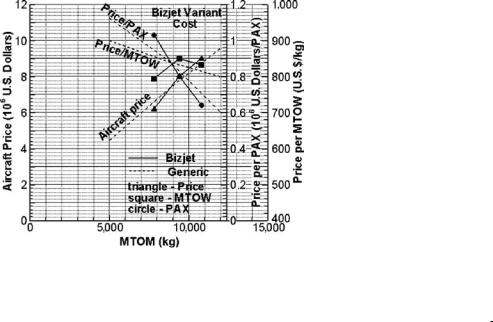
Figure 17.2. Aircraft cost factors of the worked-out Bizjet example
stock, training, and maintenance costs can be shared. Private ownership in this class is increasing and there is room for both types.
However, modifications to the smaller variant can improve the index Kn smaller. If re-engined with a smaller turbofan (i.e., the Williams type) and re-engineered with lighter and less expensive equipment, the aircraft price could be decreased to about $5 million, making it even more attractive; however, it loses some component commonality and incurs additional development costs. If the wing tips can be shortened at practically no extra cost, then the weight can be decreased to less than 7,000 kg, and the index can reach a value of more than 1.
Design for customer can help manufacturers establish the aircraft price for a family of variants, giving each type a comparative value for the customer. Typically, the smaller variant should be priced lower with a smaller profit; other aircraft prices are adjusted, with the baseline aircraft price unchanged. That is, the price of the larger aircraft can be increased to compensate the family price structure. The goal of the baseline size is maximum sales. In the example, the price of the smaller variant is $6 million, resulting in a small profit. The baseline aircraft aims for the most sales to maximize profit.
In general, route traffic load continues to increase; consequently, sales of the larger variant also increase and also the associated profits for the manufacturer, making up for the relatively smaller profit from the smaller variants. When a new market emerges for a larger traffic load, manufacturers seize the opportunity for a new baseline design.
The aircraft price per passenger and unit mass are explained herein. There is a sharp increase in per-passenger price with a smaller payload, as shown in Figure 17.2. In the figure, the dashed lines represent generic data; it is a magnified version of Figure 16.2. The solid lines represent the Bizjet family. The smaller aircraft price is slightly depressed to suit the market.
17.10 Digital Manufacturing Process Management
The digital manufacturing process management is a newer concept and is still evolving; it is software-driven. Although the industry has already deployed digital
17.10 Digital Manufacturing Process Management |
569 |
manufacturing in some areas, the full scope of application is yet to stabilize. This section describes a model briefly studied at the QUB [7]. It outlines the nature of changes taking place. These types of studies are conducted in many places, proposing many different models. The core fact is that digital manufacture is here to stay, grow, and replace or merge with traditional manufacturing philosophies.
Today, the microprocessor-driven digital manufacturing process is rapidly overtaking older methods. In fact, all modern production plants are already using it to the extent that it can be advanced. The advantage of microprocessor-based tools is that they are digitally controlled and driven by software. These tools deliver the desired “quantum leap” in manufacturing assembly techniques for future aircraft. This section outlines the role of MPM and identifies the benefits of PLM through the reconciliation perspective (i.e., estimation versus actual) between design and manufacturing engineering disciplines. PLM is a business strategy and part of MPM as a management strategy. (Life cycle is used in a generic sense, meaning all aspects of a product, from concept to retirement.)
Digital-manufacturing solutions enable the continuous creation and validation of the manufacturing processes throughout a product’s life cycle. It allows manufacturers to digitally plan, create, monitor, and control production and maintenance processes, providing complete coverage of the manufacturing processes. With the advent of new processes and techniques, there has been a greater use of software in the design and engineering of aircraft. CAD, CAM, CAE, and CAPP tools are now used to determine electronically how an aircraft system must be built. NC machines are linked with CAM.
The new frontier with software suites focuses on PLM, emphasizing the manufacturing processes. PLM is a business strategy that allows companies to share product data, apply common processes, and leverage corporate knowledge to develop products from conception to retirement across the extended enterprise. By including all participants in this process (i.e., company departments, business partners, suppliers, and operators and customers), PLM enables the entire network to operate as a single entity to conceptualize, design, build, and support products.
MPM is segmented into process detailing and validation, resource modeling, and process planning simulation. Within each segment are several modules, discussed as follows.
Process Detailing and Validation
This software suite provides engineers with the tools to bring the process planning solutions into the application-specific disciplines of manufacturing. It assists engineers in verifying process methodologies with actual product geometry and defining processes within a 3D environment. The human module offers tools that allow users to manipulate accurate, standard, digital, human mannequins, referred to as “workers,” and to simulate task activities in the process-simulation environment. Thus, worker processes can be analyzed early in the manufacturing and assembly life cycle. The assembly process simulation module sets a new paradigm for developing manufacturing and maintenance processes. It offers manufacturing engineers and assembly process planners an end-to-end solution by incorporating a single, unified interface for preplanning, detailed planning, process verification, and shop-floor instructions.
570 |
Aircraft Manufacturing Considerations |
Resource Modeling and Simulation
This software suite provides engineers with the tools to develop, create, and implement resource, mechanical programming, and application routines that are integral to the process planning and the process detailing and validation solutions. Within this set of solutions, resources such as robots, tooling, fixtures, machinery, automation, and ergonomics are defined for completing a manufacturing solution. Digital manufacturing also offers flexible, object-based, discrete event-simulation tools for efficient modeling, experimenting, and analyzing of a facility layout and process flow. Both 2D schematic and 3D physical models are quickly created (i.e., rapid prototyping) through pushbutton interfaces, dialog boxes, and extensive libraries. Real-time interaction enables modification of model variables and viewing parameters during runs.
Process Planning and Simulation
The process planning software suite provides an effective process and resourceplanning support environment. It improves methodically structured planning, early recognition of process risks, reuse of proven processes, traceable changes and decisions, and the use of scattered-process knowledge. The module is often used during the conceptual design phase, with the process-design and alternative-manufacturing concepts maturing through all the stages to production. The treatment of the relationships among product, process, and manufacturing resource data, including the plant layout, helps to avoid planning mistakes and to obtain a precise overview of the needed investment costs, production space, and manpower at an early stage.
17.10.1 Product, Process, and Resource Hub
Digital manufacturing allows manufacturing engineers and process planners to define, validate, manage, and deliver to the shop floor the content needed to manufacture an aircraft. The combination of this PPR hub environment is uniquely able to provide savings to an enterprise in the following ways by reducing risk, time to market, and overall costs of manufacturing:
Concurrent engineering design and manufacturing planning and process validation occur before release is final, in the midst of ongoing change.
Manufacturing producibility analysis directly influences design, thus providing a true DFM/A environment.
The enterprise is able to formally capture and reuse manufacturing best practices.
Manufacturing plans are prevalidated in a 3D environment to avoid unexpected problems on the shop floor.
Unbuildable conditions are found early in the design cycle when the cost of change is minimal.
Quality targets are met sooner due to reduction (or elimination) of reworking and engineering change orders generated on the shop floor.
Through a combination of methodologies, significant reductions can be achieved in time to market, overall cost, and effective risk for an aircraft program. A key enabler for reducing the time to market is the ability to support concurrent engineering
17.10 Digital Manufacturing Process Management |
571 |
design and manufacturing planning before a release is final. When this is possible, manufacturing producibility analysis directly influences design, thus providing a true DFM/A environment. In this scenario, the total costs of the engineering changes that occur during the program are dramatically less because they are identified and resolved much earlier in the life cycle. The total effective cost of the changes is dramatically less because they are mostly identified and resolved before tooling is procured and production starts.
The key technology enabler for the digital manufacturing solution, product/process design, and validation is the PPR hub and business transformation. This database environment – supporting complex configuration and affectivity rules that are required in the aerospace world – provides the infrastructure to allow process and resource planning to occur in the context of the engineering data and continuously changing environment. In contrast to traditional systems, the PPR hub provides the means to explicitly manage PPR objects and the relationships among them. Because such relationships are explicitly defined and managed within the database, it is possible to see directly the impact of changes of one object class on any other (e.g., “If a part is changed, which manufacturing plans are affected?”).
17.10.2 Integration of CAD/CAM, Manufacturing, Operations,
and In-Service Domains
One of the major areas for improvement within an aerospace enterprise is in the integration among engineering, manufacturing, and operations organizations. The drivers for such integration are to allow the maximum reuse and appropriate consolidation of data and business systems throughout the program life cycle. The degree to which this is achieved typically has a major influence on overall costs, both recurring and nonrecurring. Traditionally, the engineering and manufacturing (i.e., CAD and CAM) domains operate in a self-contained operating unit. As a result, it is difficult – if not impossible – to actually leverage engineering data downstream in the shop-floor operations area where typically bills of material (BOMs) are defined, along with related procurement data and shop-floor work instructions. One major problem with this traditional scenario is that effectively managing engineering changes and reconciling the parallel worlds of CAD and CAM and shopfloor operations is extremely difficult and expensive to do accurately. Digital manufacturing provides a means to integrate these two domains (i.e., CAD/CAM and operations), as well as the in-service domain, through several core technologies and application layers.
An additional benefit of this type of integration is the ability to reduce the number of redundant business systems between the CAD/CAM and operations organizations. This reduces recurring and overhead costs. Specifically, the following classes of business systems can be consolidated into the PPR-hub–based solution suite:
parts list and tool list
BOM definition
bill of resources
routings
process sheets/work instructions