

15.8 Aircraft Flight Deck (Cockpit) Layout |
497 |
Figure 15.14. Inflatable escape chute and slide
Coursework Exercise
There is a coursework exercise in this chapter. The configuration developed in Chapter 6 is to be reverified. The Bizjet must have the following features:
Version |
Number of Passengers |
Emergency-Door Type |
Baseline |
10 |
1 Type III and 1 Type IV |
Long |
14 |
1 Type III and 1 Type IV |
Short |
6 |
1 Type IV |
It is best for all doors to have Type III standards for component commonality, which reduces production costs.
15.8 Aircraft Flight Deck (Cockpit) Layout
The aircraft flight deck is a better term than the older usage of the word cockpit, which originated in ship design in the sixteenth century; it was similar to men working in a confined area under stress, like cocks that were forced to fight in a pit for sport. Crew station is another term meaning the same as a workplace for operators of any type of vehicle. To standardize terminology, this book uses flight deck, intended specifically for aircraft. The flight deck serves as a human–machine interface by providing (1) an outside reference of topography through the cabin windows, (2) onboard instruments to measure flight parameters, (3) control facilities to operate an aircraft safely for the mission role, and (4) management of aircraft systems (e.g., the internal environment). Future designs with advanced displays could result in a visually closed flight deck (i.e., a TV replacing the windows). The frontfuselage shape can be influenced by the flight-deck design. Transport aircraft have two pilots sitting next to one another at a pitch of about 1.2 meters in smaller aircraft to 1.4 meters in larger aircraft. Understanding the flight-deck arrangements also provides a sense of the equipment requirements that result in a measure of the associated weights involved. The space and adequacy of vision polar, which establishes the window-size requirements, also can be better understood.
498 |
Miscellaneous Design Considerations |
Both civil and military aircraft pilots have the following common functions:
mission management (planning, checks, takeoff, climb cruise, descent, and landing)
flight-path control
systems management
communication
navigation
routine postflight debriefing
emergency action when required (drills differ between civil and military aircraft)
Civil aircraft pilots are assisted by ground control (i.e., communication and navigation), whereas in a critical situation, combat pilots must manage the aircraft themselves – which is a significant difference. Both situations may require taking emergency actions, but for a combat pilot, this could be drastic in nature (i.e., ejection; see Section 15.10). In addition, military aircraft pilots have an intense workload, as follows:
mission planning (e.g., Lo/High combination; see Chapter 13); this is required for mission management (preflight briefing may change if the situation demands)
target acquisition
weapons management and delivery
defensive measures and maneuvers
counterthreats; use of tactics
management of situation when hit
in-flight refueling, where applicable
detailed postflight briefing in special situations
The military aircraft flight deck is under more stringent design requirements. The civil aircraft flight-deck design is in the wake of military standards and the provision of space is less constrained. This is why the military aircraft flight deck is discussed first (see Figure 15.16). An aircraft flight-deck design has changed dramatically since the early analog-dial displays (i.e., four-engine aircraft gauges now fill the front panel; see Figure 15.17) to modern microprocessor-based data management in an integrated, all-glass, multifunctional display (MFD), which is also known as an electronic flight information system (EFIS).
15.8.1 Multifunctional Display and Electronic Flight Information System
MFD started as a display on a cathode ray tube (CRT) but has advanced to a liquid crystal display (LCD), which is a lighter and clearer technology. All relevant data for pilot use (e.g., air, engine, and navigational data) are displayed simultaneously on the screen. To reduce clutter, the displays are divided into primary and secondary displays. Separate-system displays are accommodated in one or two
15.8 Aircraft Flight Deck (Cockpit) Layout |
499 |
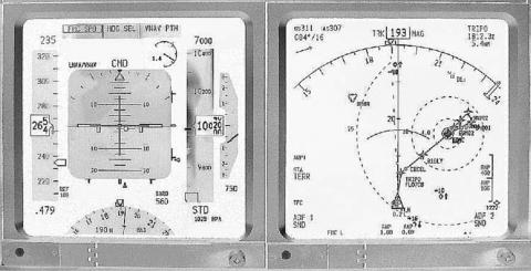
(a) Air-Data Systems Display |
(b) Navigational Display |
Figure 15.15. Multifunctional display
EFISs: the primary air-data system display (SD), and the navigational display (ND); each type of system has several pages and each display screen can be changed for specific information. Figure 15.15 shows typical EFIS displays. EFIS/MFD/ND/SD have many pages that can be flipped to as desired, including pages for the engine, cruise, flight-control, fuel, electrical, avionics, oxygen, air-bleed, air-conditioning, cabin-pressurization, hydraulics, undercarriage, doors, and the APU (military aircraft have weapons-management pages).
The primary flight display (PFD) consists of air-data systems, including aircraft speed, altitude, attitude, aircraft reference, and ambient conditions. The secondary system consists of the ND, which provides directional bearings (i.e., GPS and inertial system), flight plan, route information, weather information, airport information, and so forth. For pilot facility, each type has some duplication. In a separate panel, the SD shows the engine data and all other system data, including those required for the ECS. EFISs have removed the clutter of analog dials, one for each type of data. In some designs, the engine display (ED) is shown separately. Forwardlooking weather radar can have the ND or a separate display unit.
Initially, flight decks also had basic analog gauges showing air data as redundancies in case the EFIS failed. Currently, with vastly improved reliability in the EFIS, older analog gauges are gradually being removed.
15.8.2 Combat Aircraft Flight Deck
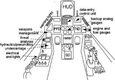
Figure 15.16 shows a typical modern flight deck for military aircraft. Backup analog gauges are provided as well as the MFD-type EFIS. The left-hand side is the throttle and the right-hand side is the side-stick controller known as the hands-on throttle and stick (HOTAS) (see Section 15.8.6). The figure indicates which type of data and control a pilot requires. A single pilot’s workload is exceptionally high when computer assistance is required.
500 |
Miscellaneous Design Considerations |
Flight data EFIS at the left and navigational data EFIS at the right
Figure 15.16. Schematic fighter-aircraft flight deck
15.8.3 Civil Aircraft Flight Deck
An old-type panel with analog dial gauges is shown in Figure 15.17. With two pilots, some of the displays are duplicated, which are deliberate redundancies.
The latest Airbus 380 flight-deck panel replaces myriad gauges by EFISs, which are MFD units. The minimum generic layout of a modern flight-deck panel is shown in Figure 15.18. Numerous redundancies are built into the display with independent circuits. PFDs, NDs, and SDs have several pages that display significant data.
15.8.4 Head-Up Display
The flight-deck displays shown in Figures 15.16 through 15.18 are on the instrument panel in front of the pilot, who must look down for flight information – more frequently in critical situations. When flying close to the ground or chasing a target, however, pilots should keep their head up, looking for external references. This inflicts severe strain on pilots who must frequently alternate the head-up and headdown positions. Engineers have solved the problem to a great extent by projecting the most important flight information (both primary and navigational data) in bright green light on transparent glass mounted in front of the windscreen. With a headup display (HUD), pilots can see all necessary information without moving their head and, at the same time, they can see through the HUD for external references. Figures 15.17 and 15.18 show a modern HUD.
Initially, a HUD was installed in combat aircraft but the technology recently has trickled into civil aviation as well. HUDs are being installed on most new mediumand large-sized commercial transport aircraft if requested by operators.