

- •Contents
- •Symbols and Abbreviations
- •Symbols
- •Greek Symbols
- •Subscripts
- •Abbreviations
- •Preface
- •Road Map of the Book
- •The Arrangement
- •Suggested Route for the Coursework
- •First Semester
- •Second Semester
- •Suggestions for the Class
- •Use of Semi-empirical Relations
- •1 Introduction
- •1.1 Overview
- •1.1.1 What Is to Be Learned?
- •1.1.2 Coursework Content
- •1.2 Brief Historical Background
- •1.3 Current Aircraft Design Status
- •1.3.1 Forces and Drivers
- •1.3.2 Current Civil Aircraft Design Trends
- •1.3.3 Current Military Aircraft Design Trends
- •1.4 Future Trends
- •1.4.1 Civil Aircraft Design: Future Trends
- •1.4.2 Military Aircraft Design: Future Trends
- •1.5 Learning Process
- •1.6 Units and Dimensions
- •1.7 Cost Implications
- •2 Methodology to Aircraft Design, Market Survey, and Airworthiness
- •2.1 Overview
- •2.1.1 What Is to Be Learned?
- •2.1.2 Coursework Content
- •2.2 Introduction
- •2.3 Typical Design Process
- •2.3.1 Four Phases of Aircraft Design
- •2.3.2 Typical Resources Deployment
- •2.3.3 Typical Cost Frame
- •2.3.4 Typical Time Frame
- •2.4 Typical Task Breakdown in Each Phase
- •Phase 1: Conceptual Study Phase (Feasibility Study)
- •Phase 3: Detailed Design Phase (Full-Scale Product Development)
- •2.4.1 Functional Tasks during the Conceptual Study (Phase 1: Civil Aircraft)
- •2.4.2 Project Activities for Small Aircraft Design
- •Phase 1: Conceptual Design (6 Months)
- •Phase 3: Detailed Design (Product Development) (12 Months)
- •2.5 Aircraft Familiarization
- •Fuselage Group
- •Wing Group
- •Empennage Group
- •Nacelle Group
- •Undercarriage Group
- •2.6 Market Survey
- •2.7 Civil Aircraft Market
- •2.8 Military Market
- •2.9 Comparison between Civil and Military Aircraft Design Requirements
- •2.10 Airworthiness Requirements
- •2.11 Coursework Procedures
- •3 Aerodynamic Considerations
- •3.1 Overview
- •3.1.1 What Is to Be Learned?
- •3.1.2 Coursework Content
- •3.2 Introduction
- •3.3 Atmosphere
- •3.4 Fundamental Equations
- •3.5.1 Flow Past Aerofoil
- •3.6 Aircraft Motion and Forces
- •3.6.1 Motion
- •3.6.2 Forces
- •3.7 Aerofoil
- •3.7.1 Groupings of Aerofoils and Their Properties
- •NACA Four-Digit Aerofoil
- •NACA Five-Digit Aerofoil
- •NACA Six-Digit Aerofoil
- •Other Types of Aerofoils
- •3.9 Generation of Lift
- •3.10 Types of Stall
- •3.10.1 Gradual Stall
- •3.10.2 Abrupt Stall
- •3.11 Comparison of Three NACA Aerofoils
- •3.12 High-Lift Devices
- •3.13 Transonic Effects – Area Rule
- •3.14 Wing Aerodynamics
- •3.14.1 Induced Drag and Total Aircraft Drag
- •3.15 Aspect Ratio Correction of 2D Aerofoil Characteristics for 3D Finite Wing
- •3.16.1 Planform Area, SW
- •3.16.2 Wing Aspect Ratio
- •3.16.4 Wing Root (Croot) and Tip (Ctip) Chord
- •3.16.6 Wing Twist
- •3.17 Mean Aerodynamic Chord
- •3.18 Compressibility Effect: Wing Sweep
- •3.19 Wing Stall Pattern and Wing Twist
- •3.20.1 The Square-Cube Law
- •3.20.2 Aircraft Wetted Area (AW) versus Wing Planform Area (Sw)
- •3.20.3 Additional Vortex Lift
- •3.20.4 Additional Surfaces on Wing
- •3.21 Finalizing Wing Design Parameters
- •3.22 Empennage
- •3.22.1 H-Tail
- •3.22.2 V-Tail
- •3.23 Fuselage
- •3.23.2 Fuselage Length, Lfus
- •3.23.3 Fineness Ratio, FR
- •3.23.4 Fuselage Upsweep Angle
- •3.23.5 Fuselage Closure Angle
- •3.23.6 Front Fuselage Closure Length, Lf
- •3.23.7 Aft Fuselage Closure Length, La
- •3.23.8 Midfuselage Constant Cross-Section Length, Lm
- •3.23.9 Fuselage Height, H
- •3.23.10 Fuselage Width, W
- •3.23.11 Average Diameter, Dave
- •3.23.12 Cabin Height, Hcab
- •3.23.13 Cabin Width, Wcab
- •3.24 Undercarriage
- •3.25 Nacelle and Intake
- •3.26 Speed Brakes and Dive Brakes
- •4.1 Overview
- •4.1.1 What Is to Be Learned?
- •4.1.2 Coursework Content
- •4.2 Introduction
- •4.3 Aircraft Evolution
- •4.4 Civil Aircraft Mission (Payload-Range)
- •4.5 Civil Subsonic Jet Aircraft Statistics (Sizing Parameters and Regression Analysis)
- •4.5.1 Maximum Takeoff Mass versus Number of Passengers
- •4.5.2 Maximum Takeoff Mass versus Operational Empty Mass
- •4.5.3 Maximum Takeoff Mass versus Fuel Load
- •4.5.4 Maximum Takeoff Mass versus Wing Area
- •4.5.5 Maximum Takeoff Mass versus Engine Power
- •4.5.6 Empennage Area versus Wing Area
- •4.5.7 Wing Loading versus Aircraft Span
- •4.6 Civil Aircraft Component Geometries
- •4.7 Fuselage Group
- •4.7.1 Fuselage Width
- •4.7.2 Fuselage Length
- •4.7.3 Front (Nose Cone) and Aft-End Closure
- •4.7.4 Flight Crew (Flight Deck) Compartment Layout
- •4.7.5 Cabin Crew and Passenger Facilities
- •4.7.6 Seat Arrangement, Pitch, and Posture (95th Percentile) Facilities
- •4.7.7 Passenger Facilities
- •4.7.8 Cargo Container Sizes
- •4.7.9 Doors – Emergency Exits
- •4.8 Wing Group
- •4.9 Empennage Group (Civil Aircraft)
- •4.10 Nacelle Group
- •4.11 Summary of Civil Aircraft Design Choices
- •4.13 Military Aircraft Mission
- •4.14.1 Military Aircraft Maximum Take-off Mass (MTOM) versus Payload
- •4.14.2 Military MTOM versus OEM
- •4.14.3 Military MTOM versus Fuel Load Mf
- •4.14.4 MTOM versus Wing Area (Military)
- •4.14.5 MTOM versus Engine Thrust (Military)
- •4.14.6 Empennage Area versus Wing Area (Military)
- •4.14.7 Aircraft Wetted Area versus Wing Area (Military)
- •4.15 Military Aircraft Component Geometries
- •4.16 Fuselage Group (Military)
- •4.17 Wing Group (Military)
- •4.17.1 Generic Wing Planform Shapes
- •4.18 Empennage Group (Military)
- •4.19 Intake/Nacelle Group (Military)
- •4.20 Undercarriage Group
- •4.21 Miscellaneous Comments
- •4.22 Summary of Military Aircraft Design Choices
- •5 Aircraft Load
- •5.1 Overview
- •5.1.1 What Is to Be Learned?
- •5.1.2 Coursework Content
- •5.2 Introduction
- •5.2.1 Buffet
- •5.2.2 Flutter
- •5.3 Flight Maneuvers
- •5.3.1 Pitch Plane (X-Z) Maneuver (Elevator/Canard-Induced)
- •5.3.2 Roll Plane (Y-Z) Maneuver (Aileron-Induced)
- •5.3.3 Yaw Plane (Z-X) Maneuver (Rudder-Induced)
- •5.4 Aircraft Loads
- •5.4.1 On the Ground
- •5.4.2 In Flight
- •5.5.1 Load Factor, n
- •5.6 Limits – Load and Speeds
- •5.6.1 Maximum Limit of Load Factor
- •5.6.2 Speed Limits
- •5.7 V-n Diagram
- •5.7.1 Low-Speed Limit
- •5.7.2 High-Speed Limit
- •5.7.3 Extreme Points of a V-n Diagram
- •Positive Loads
- •Negative Loads
- •5.8 Gust Envelope
- •6.1 Overview
- •6.1.1 What Is to Be Learned?
- •6.1.2 Coursework Content
- •6.2 Introduction
- •Closure of the Fuselage
- •6.4 Civil Aircraft Fuselage: Typical Shaping and Layout
- •6.4.1 Narrow-Body, Single-Aisle Aircraft
- •6.4.2 Wide-Body, Double-Aisle Aircraft
- •6.4.3 Worked-Out Example: Civil Aircraft Fuselage Layout
- •6.5.1 Aerofoil Selection
- •6.5.2 Wing Design
- •Planform Shape
- •Wing Reference Area
- •Wing Sweep
- •Wing Twist
- •Wing Dihedral/Anhedral
- •6.5.3 Wing-Mounted Control-Surface Layout
- •6.5.4 Positioning of the Wing Relative to the Fuselage
- •6.6.1 Horizontal Tail
- •6.6.2 Vertical Tail
- •6.8 Undercarriage Positioning
- •6.10 Miscellaneous Considerations in Civil Aircraft
- •6.12.1 Use of Statistics in the Class of Military Trainer Aircraft
- •6.12.3 Miscellaneous Considerations – Military Design
- •6.13 Variant CAS Design
- •6.13.1 Summary of the Worked-Out Military Aircraft Preliminary Details
- •7 Undercarriage
- •7.1 Overview
- •7.1.1 What Is to Be Learned?
- •7.1.2 Coursework Content
- •7.2 Introduction
- •7.3 Types of Undercarriage
- •7.5 Undercarriage Retraction and Stowage
- •7.5.1 Stowage Space Clearances
- •7.6 Undercarriage Design Drivers and Considerations
- •7.7 Turning of an Aircraft
- •7.8 Wheels
- •7.9 Loads on Wheels and Shock Absorbers
- •7.9.1 Load on Wheels
- •7.9.2 Energy Absorbed
- •7.11 Tires
- •7.13 Undercarriage Layout Methodology
- •7.14 Worked-Out Examples
- •7.14.1 Civil Aircraft: Bizjet
- •Baseline Aircraft with 10 Passengers at a 33-Inch Pitch
- •Shrunk Aircraft (Smallest in the Family Variant) with 6 Passengers at a 33-Inch Pitch
- •7.14.2 Military Aircraft: AJT
- •7.15 Miscellaneous Considerations
- •7.16 Undercarriage and Tire Data
- •8 Aircraft Weight and Center of Gravity Estimation
- •8.1 Overview
- •8.1.1 What Is to Be Learned?
- •8.1.2 Coursework Content
- •8.2 Introduction
- •8.3 The Weight Drivers
- •8.4 Aircraft Mass (Weight) Breakdown
- •8.5 Desirable CG Position
- •8.6 Aircraft Component Groups
- •8.6.1 Civil Aircraft
- •8.6.2 Military Aircraft (Combat Category)
- •8.7 Aircraft Component Mass Estimation
- •8.8 Rapid Mass Estimation Method: Civil Aircraft
- •8.9 Graphical Method for Predicting Aircraft Component Weight: Civil Aircraft
- •8.10 Semi-empirical Equation Method (Statistical)
- •8.10.1 Fuselage Group – Civil Aircraft
- •8.10.2 Wing Group – Civil Aircraft
- •8.10.3 Empennage Group – Civil Aircraft
- •8.10.4 Nacelle Group – Civil Aircraft
- •Jet Type (Includes Pylon Mass)
- •Turboprop Type
- •Piston-Engine Nacelle
- •8.10.5 Undercarriage Group – Civil Aircraft
- •Tricycle Type (Retractable) – Fuselage-Mounted (Nose and Main Gear Estimated Together)
- •8.10.6 Miscellaneous Group – Civil Aircraft
- •8.10.7 Power Plant Group – Civil Aircraft
- •Turbofans
- •Turboprops
- •Piston Engines
- •8.10.8 Systems Group – Civil Aircraft
- •8.10.9 Furnishing Group – Civil Aircraft
- •8.10.10 Contingency and Miscellaneous – Civil Aircraft
- •8.10.11 Crew – Civil Aircraft
- •8.10.12 Payload – Civil Aircraft
- •8.10.13 Fuel – Civil Aircraft
- •8.11 Worked-Out Example – Civil Aircraft
- •8.11.1 Fuselage Group Mass
- •8.11.2 Wing Group Mass
- •8.11.3 Empennage Group Mass
- •8.11.4 Nacelle Group Mass
- •8.11.5 Undercarriage Group Mass
- •8.11.6 Miscellaneous Group Mass
- •8.11.7 Power Plant Group Mass
- •8.11.8 Systems Group Mass
- •8.11.9 Furnishing Group Mass
- •8.11.10 Contingency Group Mass
- •8.11.11 Crew Mass
- •8.11.12 Payload Mass
- •8.11.13 Fuel Mass
- •8.11.14 Weight Summary
- •Variant Aircraft in the Family
- •8.12 Center of Gravity Determination
- •8.12.1 Bizjet Aircraft CG Location Example
- •8.12.2 First Iteration to Fine Tune CG Position Relative to Aircraft and Components
- •8.13 Rapid Mass Estimation Method – Military Aircraft
- •8.14 Graphical Method to Predict Aircraft Component Weight – Military Aircraft
- •8.15 Semi-empirical Equation Methods (Statistical) – Military Aircraft
- •8.15.1 Military Aircraft Fuselage Group (SI System)
- •8.15.2 Military Aircraft Wing Mass (SI System)
- •8.15.3 Military Aircraft Empennage
- •8.15.4 Nacelle Mass Example – Military Aircraft
- •8.15.5 Power Plant Group Mass Example – Military Aircraft
- •8.15.6 Undercarriage Mass Example – Military Aircraft
- •8.15.7 System Mass – Military Aircraft
- •8.15.8 Aircraft Furnishing – Military Aircraft
- •8.15.11 Crew Mass
- •8.16.1 AJT Fuselage Example (Based on CAS Variant)
- •8.16.2 AJT Wing Example (Based on CAS Variant)
- •8.16.3 AJT Empennage Example (Based on CAS Variant)
- •8.16.4 AJT Nacelle Mass Example (Based on CAS Variant)
- •8.16.5 AJT Power Plant Group Mass Example (Based on AJT Variant)
- •8.16.6 AJT Undercarriage Mass Example (Based on CAS Variant)
- •8.16.7 AJT Systems Group Mass Example (Based on AJT Variant)
- •8.16.8 AJT Furnishing Group Mass Example (Based on AJT Variant)
- •8.16.9 AJT Contingency Group Mass Example
- •8.16.10 AJT Crew Mass Example
- •8.16.13 Weights Summary – Military Aircraft
- •8.17 CG Position Determination – Military Aircraft
- •8.17.1 Classroom Worked-Out Military AJT CG Location Example
- •8.17.2 First Iteration to Fine Tune CG Position and Components Masses
- •9 Aircraft Drag
- •9.1 Overview
- •9.1.1 What Is to Be Learned?
- •9.1.2 Coursework Content
- •9.2 Introduction
- •9.4 Aircraft Drag Breakdown (Subsonic)
- •9.5 Aircraft Drag Formulation
- •9.6 Aircraft Drag Estimation Methodology (Subsonic)
- •9.7 Minimum Parasite Drag Estimation Methodology
- •9.7.2 Computation of Wetted Areas
- •Lifting Surfaces
- •Fuselage
- •Nacelle
- •9.7.3 Stepwise Approach to Compute Minimum Parasite Drag
- •9.8 Semi-empirical Relations to Estimate Aircraft Component Parasite Drag
- •9.8.1 Fuselage
- •9.8.2 Wing, Empennage, Pylons, and Winglets
- •9.8.3 Nacelle Drag
- •Intake Drag
- •Base Drag
- •Boat-Tail Drag
- •9.8.4 Excrescence Drag
- •9.8.5 Miscellaneous Parasite Drags
- •Air-Conditioning Drag
- •Trim Drag
- •Aerials
- •9.9 Notes on Excrescence Drag Resulting from Surface Imperfections
- •9.10 Minimum Parasite Drag
- •9.12 Subsonic Wave Drag
- •9.13 Total Aircraft Drag
- •9.14 Low-Speed Aircraft Drag at Takeoff and Landing
- •9.14.1 High-Lift Device Drag
- •9.14.2 Dive Brakes and Spoilers Drag
- •9.14.3 Undercarriage Drag
- •9.14.4 One-Engine Inoperative Drag
- •9.15 Propeller-Driven Aircraft Drag
- •9.16 Military Aircraft Drag
- •9.17 Supersonic Drag
- •9.18 Coursework Example: Civil Bizjet Aircraft
- •9.18.1 Geometric and Performance Data
- •Fuselage (see Figure 9.13)
- •Wing (see Figure 9.13)
- •Empennage (see Figure 9.13)
- •Nacelle (see Figure 9.13)
- •9.18.2 Computation of Wetted Areas, Re, and Basic CF
- •Fuselage
- •Wing
- •Empennage (same procedure as for the wing)
- •Nacelle
- •Pylon
- •9.18.3 Computation of 3D and Other Effects to Estimate Component
- •Fuselage
- •Wing
- •Empennage
- •Nacelle
- •Pylon
- •9.18.4 Summary of Parasite Drag
- •9.18.5 CDp Estimation
- •9.18.6 Induced Drag
- •9.18.7 Total Aircraft Drag at LRC
- •9.19 Coursework Example: Subsonic Military Aircraft
- •9.19.1 Geometric and Performance Data of a Vigilante RA-C5 Aircraft
- •Fuselage
- •Wing
- •Empennage
- •9.19.2 Computation of Wetted Areas, Re, and Basic CF
- •Fuselage
- •Wing
- •Empennage (same procedure as for the wing)
- •9.19.3 Computation of 3D and Other Effects to Estimate Component CDpmin
- •Fuselage
- •Wing
- •Empennage
- •9.19.4 Summary of Parasite Drag
- •9.19.5 CDp Estimation
- •9.19.6 Induced Drag
- •9.19.7 Supersonic Drag Estimation
- •9.19.8 Total Aircraft Drag
- •9.20 Concluding Remarks
- •10 Aircraft Power Plant and Integration
- •10.1 Overview
- •10.1.1 What Is to Be Learned?
- •10.1.2 Coursework Content
- •10.2 Background
- •10.4 Introduction: Air-Breathing Aircraft Engine Types
- •10.4.1 Simple Straight-Through Turbojet
- •10.4.2 Turbofan: Bypass Engine
- •10.4.3 Afterburner Engine
- •10.4.4 Turboprop Engine
- •10.4.5 Piston Engine
- •10.6 Formulation and Theory: Isentropic Case
- •10.6.1 Simple Straight-Through Turbojet Engine: Formulation
- •10.6.2 Bypass Turbofan Engine: Formulation
- •10.6.3 Afterburner Engine: Formulation
- •10.6.4 Turboprop Engine: Formulation
- •Summary
- •10.7 Engine Integration with an Aircraft: Installation Effects
- •10.7.1 Subsonic Civil Aircraft Nacelle and Engine Installation
- •10.7.2 Turboprop Integration to Aircraft
- •10.7.3 Combat Aircraft Engine Installation
- •10.8 Intake and Nozzle Design
- •10.8.1 Civil Aircraft Intake Design: Inlet Sizing
- •10.8.2 Military Aircraft Intake Design
- •10.9 Exhaust Nozzle and Thrust Reverser
- •10.9.1 Civil Aircraft Thrust Reverser Application
- •10.9.2 Civil Aircraft Exhaust Nozzles
- •10.9.3 Coursework Example of Civil Aircraft Nacelle Design
- •Intake Geometry (see Section 10.8.1)
- •Lip Section (Crown Cut)
- •Lip Section (Keel Cut)
- •Nozzle Geometry
- •10.9.4 Military Aircraft Thrust Reverser Application and Exhaust Nozzles
- •10.10 Propeller
- •10.10.2 Propeller Theory
- •Momentum Theory: Actuator Disc
- •Blade-Element Theory
- •10.10.3 Propeller Performance: Practical Engineering Applications
- •Static Performance (see Figures 10.34 and 10.36)
- •In-Flight Performance (see Figures 10.35 and 10.37)
- •10.10.5 Propeller Performance at STD Day: Worked-Out Example
- •10.11 Engine-Performance Data
- •Takeoff Rating
- •Maximum Continuous Rating
- •Maximum Climb Rating
- •Maximum Cruise Rating
- •Idle Rating
- •10.11.1 Piston Engine
- •10.11.2 Turboprop Engine (Up to 100 Passengers Class)
- •Takeoff Rating
- •Maximum Climb Rating
- •Maximum Cruise Rating
- •10.11.3 Turbofan Engine: Civil Aircraft
- •Turbofans with a BPR Around 4 (Smaller Engines; e.g., Bizjets)
- •Turbofans with a BPR around 5 or 7 (Larger Engines; e.g., RJs and Larger)
- •10.11.4 Turbofan Engine – Military Aircraft
- •11 Aircraft Sizing, Engine Matching, and Variant Derivative
- •11.1 Overview
- •11.1.1 What Is to Be Learned?
- •11.1.2 Coursework Content
- •11.2 Introduction
- •11.3 Theory
- •11.3.1 Sizing for Takeoff Field Length
- •Civil Aircraft Design: Takeoff
- •Military Aircraft Design: Takeoff
- •11.3.2 Sizing for the Initial Rate of Climb
- •11.3.3 Sizing to Meet Initial Cruise
- •11.3.4 Sizing for Landing Distance
- •11.4 Coursework Exercises: Civil Aircraft Design (Bizjet)
- •11.4.1 Takeoff
- •11.4.2 Initial Climb
- •11.4.3 Cruise
- •11.4.4 Landing
- •11.5 Coursework Exercises: Military Aircraft Design (AJT)
- •11.5.1 Takeoff – Military Aircraft
- •11.5.2 Initial Climb – Military Aircraft
- •11.5.3 Cruise – Military Aircraft
- •11.5.4 Landing – Military Aircraft
- •11.6 Sizing Analysis: Civil Aircraft (Bizjet)
- •11.6.1 Variants in the Family of Aircraft Design
- •11.6.2 Example: Civil Aircraft
- •11.7 Sizing Analysis: Military Aircraft
- •11.7.1 Single-Seat Variant in the Family of Aircraft Design
- •11.8 Sensitivity Study
- •11.9 Future Growth Potential
- •12.1 Overview
- •12.1.1 What Is to Be Learned?
- •12.1.2 Coursework Content
- •12.2 Introduction
- •12.3 Static and Dynamic Stability
- •12.3.1 Longitudinal Stability: Pitch Plane (Pitch Moment, M)
- •12.3.2 Directional Stability: Yaw Plane (Yaw Moment, N)
- •12.3.3 Lateral Stability: Roll Plane (Roll Moment, L)
- •12.3.4 Summary of Forces, Moments, and Their Sign Conventions
- •12.4 Theory
- •12.4.1 Pitch Plane
- •12.4.2 Yaw Plane
- •12.4.3 Roll Plane
- •12.6 Inherent Aircraft Motions as Characteristics of Design
- •12.6.1 Short-Period Oscillation and Phugoid Motion
- •12.6.2 Directional and Lateral Modes of Motion
- •12.7 Spinning
- •12.8 Design Considerations for Stability: Civil Aircraft
- •12.9 Military Aircraft: Nonlinear Effects
- •12.10 Active Control Technology: Fly-by-Wire
- •13 Aircraft Performance
- •13.1 Overview
- •13.1.1 What Is to Be Learned?
- •13.1.2 Coursework Content
- •13.2 Introduction
- •13.2.1 Aircraft Speed
- •13.3 Establish Engine Performance Data
- •13.3.1 Turbofan Engine (BPR < 4)
- •Takeoff Rating (Bizjet): Standard Day
- •Maximum Climb Rating (Bizjet): Standard Day
- •Maximum Cruise Rating (Bizjet): Standard Day
- •13.3.2 Turbofan Engine (BPR > 4)
- •13.3.3 Military Turbofan (Advanced Jet Trainer/CAS Role – Very Low BPR) – STD Day
- •13.3.4 Turboprop Engine Performance
- •Takeoff Rating (Turboprop): Standard Day
- •Maximum Climb Rating (Turboprop): Standard Day
- •Maximum Cruise Rating (Turboprop): Standard Day
- •13.4 Derivation of Pertinent Aircraft Performance Equations
- •13.4.1 Takeoff
- •Balanced Field Length: Civil Aircraft
- •Takeoff Equations
- •13.4.2 Landing Performance
- •13.4.3 Climb and Descent Performance
- •Summary
- •Descent
- •13.4.4 Initial Maximum Cruise Speed
- •13.4.5 Payload Range Capability
- •13.5 Aircraft Performance Substantiation: Worked-Out Examples (Bizjet)
- •13.5.1 Takeoff Field Length (Bizjet)
- •Segment A: All Engines Operating up to the Decision Speed V1
- •Segment B: One-Engine Inoperative Acceleration from V1 to Liftoff Speed, VLO
- •Segment C: Flaring Distance with One Engine Inoperative from VLO to V2
- •Segment E: Braking Distance from VB to Zero Velocity (Flap Settings Are of Minor Consequence)
- •Discussion of the Takeoff Analysis
- •13.5.2 Landing Field Length (Bizjet)
- •13.5.3 Climb Performance Requirements (Bizjet)
- •13.5.4 Integrated Climb Performance (Bizjet)
- •13.5.5 Initial High-Speed Cruise (Bizjet)
- •13.5.7 Descent Performance (Bizjet)
- •13.5.8 Payload Range Capability
- •13.6 Aircraft Performance Substantiation: Military Aircraft (AJT)
- •13.6.2 Takeoff Field Length (AJT)
- •Distance Covered from Zero to the Decision Speed V1
- •Distance Covered from Zero to Liftoff Speed VLO
- •Distance Covered from VLO to V2
- •Total Takeoff Distance
- •Stopping Distance and the CFL
- •Distance Covered from V1 to Braking Speed VB
- •Verifying the Climb Gradient at an 8-Deg Flap
- •13.6.3 Landing Field Length (AJT)
- •13.6.4 Climb Performance Requirements (AJT)
- •13.6.5 Maximum Speed Requirements (AJT)
- •13.6.6 Fuel Requirements (AJT)
- •13.7 Summary
- •13.7.1 The Bizjet
- •14 Computational Fluid Dynamics
- •14.1 Overview
- •14.1.1 What Is to Be Learned?
- •14.1.2 Coursework Content
- •14.2 Introduction
- •14.3 Current Status
- •14.4 Approach to CFD Analyses
- •14.4.1 In the Preprocessor (Menu-Driven)
- •14.4.2 In the Flow Solver (Menu-Driven)
- •14.4.3 In the Postprocessor (Menu-Driven)
- •14.5 Case Studies
- •14.6 Hierarchy of CFD Simulation Methods
- •14.6.1 DNS Simulation Technique
- •14.6.2 Large Eddy Simulation (LES) Technique
- •14.6.3 Detached Eddy Simulation (DES) Technique
- •14.6.4 RANS Equation Technique
- •14.6.5 Euler Method Technique
- •14.6.6 Full-Potential Flow Equations
- •14.6.7 Panel Method
- •14.7 Summary
- •15 Miscellaneous Design Considerations
- •15.1 Overview
- •15.1.1 What Is to Be Learned?
- •15.1.2 Coursework Content
- •15.2 Introduction
- •15.2.1 Environmental Issues
- •15.2.2 Materials and Structures
- •15.2.3 Safety Issues
- •15.2.4 Human Interface
- •15.2.5 Systems Architecture
- •15.2.6 Military Aircraft Survivability Issues
- •15.2.7 Emerging Scenarios
- •15.3 Noise Emissions
- •Approach
- •Sideline
- •15.3.1 Summary
- •15.4 Engine Exhaust Emissions
- •15.5 Aircraft Materials
- •15.5.1 Material Properties
- •15.5.2 Material Selection
- •15.5.3 Coursework Overview
- •Civil Aircraft Design
- •Military Aircraft Design
- •15.6 Aircraft Structural Considerations
- •15.7 Doors: Emergency Egress
- •Coursework Exercise
- •15.8 Aircraft Flight Deck (Cockpit) Layout
- •15.8.1 Multifunctional Display and Electronic Flight Information System
- •15.8.2 Combat Aircraft Flight Deck
- •15.8.3 Civil Aircraft Flight Deck
- •15.8.4 Head-Up Display
- •15.8.5 Helmet-Mounted Display
- •15.8.6 Hands-On Throttle and Stick
- •15.8.7 Voice-Operated Control
- •15.9 Aircraft Systems
- •15.9.1 Aircraft Control Subsystem
- •15.9.2 Engine and Fuel Control Subsystems
- •Piston Engine Fuel Control System (The total system weight is approximately 1 to 1.5% of the MTOW)
- •Turbofan Engine Fuel Control System (The total system weight is approximately 1.5 to 2% of the MTOW)
- •Fuel Storage and Flow Management
- •15.9.3 Emergency Power Supply
- •15.9.4 Avionics Subsystems
- •Military Aircraft Application
- •Civil Aircraft Application
- •15.9.5 Electrical Subsystem
- •15.9.6 Hydraulic Subsystem
- •15.9.7 Pneumatic System
- •ECS: Cabin Pressurization and Air-Conditioning
- •Oxygen Supply
- •Anti-icing, De-icing, Defogging, and Rain-Removal Systems
- •Defogging and Rain-Removal Systems
- •15.9.8 Utility Subsystem
- •15.9.9 End-of-Life Disposal
- •15.10 Military Aircraft Survivability
- •15.10.1 Military Emergency Escape
- •15.10.2 Military Aircraft Stealth Consideration
- •15.11 Emerging Scenarios
- •Counterterrorism Design Implementation
- •Health Issues
- •Damage from Runway Debris
- •16 Aircraft Cost Considerations
- •16.1 Overview
- •16.1.1 What Is to Be Learned?
- •16.1.2 Coursework Content
- •16.2 Introduction
- •16.3 Aircraft Cost and Operational Cost
- •Operating Cost
- •16.4 Aircraft Costing Methodology: Rapid-Cost Model
- •16.4.1 Nacelle Cost Drivers
- •Group 1
- •Group 2
- •16.4.2 Nose Cowl Parts and Subassemblies
- •16.4.3 Methodology (Nose Cowl Only)
- •Cost of Parts Fabrication
- •Subassemblies
- •Cost of Amortization of the NRCs
- •16.4.4 Cost Formulas and Results
- •16.5 Aircraft Direct Operating Cost
- •16.5.1 Formulation to Estimate DOC
- •Aircraft Price
- •Fixed-Cost Elements
- •Trip-Cost Elements
- •16.5.2 Worked-Out Example of DOC: Bizjet
- •Aircraft Price
- •Fixed-Cost Elements
- •Trip-Cost Elements
- •OC of the Variants in the Family
- •17 Aircraft Manufacturing Considerations
- •17.1 Overview
- •17.1.1 What Is to Be Learned?
- •17.1.2 Coursework Content
- •17.2 Introduction
- •17.3 Design for Manufacture and Assembly
- •17.4 Manufacturing Practices
- •17.5 Six Sigma Concept
- •17.6 Tolerance Relaxation at the Wetted Surface
- •17.6.1 Sources of Aircraft Surface Degeneration
- •17.6.2 Cost-versus-Tolerance Relationship
- •17.7 Reliability and Maintainability
- •17.8 Design Considerations
- •17.8.1 Category I: Technology-Driven Design Considerations
- •17.8.2 Category II: Manufacture-Driven Design Considerations
- •17.8.3 Category III: Management-Driven Design Considerations
- •17.8.4 Category IV: Operator-Driven Design Considerations
- •17.9 “Design for Customer”
- •17.9.1 Index for “Design for Customer”
- •17.9.2 Worked-Out Example
- •Standard Parameters of the Baseline Aircraft
- •Parameters of the Extended Variant Aircraft
- •Parameters of the Shortened Variant Aircraft
- •17.10 Digital Manufacturing Process Management
- •Process Detailing and Validation
- •Resource Modeling and Simulation
- •Process Planning and Simulation
- •17.10.1 Product, Process, and Resource Hub
- •17.10.3 Shop-Floor Interface
- •17.10.4 Design for Maintainability and 3D-Based Technical Publication Generation
- •Midrange Aircraft (Airbus 320 class)
- •References
- •ROAD MAP OF THE BOOK
- •CHAPTER 1. INTRODUCTION
- •CHAPTER 3. AERODYNAMIC CONSIDERATIONS
- •CHAPTER 5. AIRCRAFT LOAD
- •CHAPTER 6. CONFIGURING AIRCRAFT
- •CHAPTER 7. UNDERCARRIAGE
- •CHAPTER 8. AIRCRAFT WEIGHT AND CENTER OF GRAVITY ESTIMATION
- •CHAPTER 9. AIRCRAFT DRAG
- •CHAPTER 10. AIRCRAFT POWER PLANT AND INTEGRATION
- •CHAPTER 11. AIRCRAFT SIZING, ENGINE MATCHING, AND VARIANT DERIVATIVE
- •CHAPTER 12. STABILITY CONSIDERATIONS AFFECTING AIRCRAFT CONFIGURATION
- •CHAPTER 13. AIRCRAFT PERFORMANCE
- •CHAPTER 14. COMPUTATIONAL FLUID DYNAMICS
- •CHAPTER 15. MISCELLANEOUS DESIGN CONSIDERATIONS
- •CHAPTER 16. AIRCRAFT COST CONSIDERATIONS
- •CHAPTER 17. AIRCRAFT MANUFACTURING CONSIDERATIONS
- •Index
15.3 Noise Emissions |
479 |
design philosophy. Automation and microprocessor-based data management have advanced to a wider operational capability without a corresponding increase in a pilot’s workload. In this way, readers can see an aircraft as a system and subsystems.
15.2.6 Military Aircraft Survivability Issues
Military aircraft design for combat survivability has been considered for some time, primarily as a consequence of potential damage occurring in combat. Crew-ejection capability is an integral part of survivability. In the last two decades, stealth technology – as a good survival measure – has advanced by minimizing an aircraft’s signature. Electronic defense and countermeasures are other ways to thwart retaliation and increase survivability.
15.2.7 Emerging Scenarios
New topics are gaining importance and must be considered by the next generation of engineers. The emerging scenarios affecting civil aviation result from acts of terrorism in recent years. Aircraft design must include damage limitation from an explosion in the cargo compartments and containment of terrorist activities within the cabin. Also, damage incurred from runway debris demands a new perspective on an old problem (i.e., the Concorde crash case). With greatly increased numbers of passengers crossing international boundaries, general health care and contagious infections are becoming important issues.
15.3 Noise Emissions
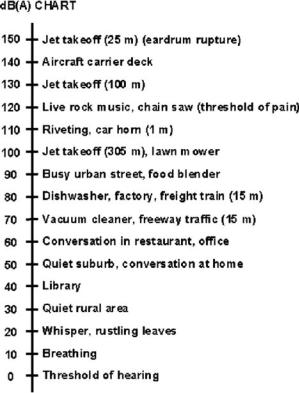
Noise is produced by pressure pulses in air generated from any vibrating source. The pulsating energy is transmitted through the air and is heard within the audible frequency range (i.e., 20 to 20,000 Hz). The intensity and frequency of pulsation determine the physical limits of human tolerance. In certain conditions, acoustic (i.e., noise) vibrations can affect an aircraft structure. Noise is perceived as environmental pollution.
The intensity of sound energy can be measured by the sound pressure level (SPL); the threshold of hearing value is 20µPa. The response of human hearing can be approximated by a logarithmic scale. The advantage of using a logarithmic scale for noise measurement is to compress the SPL range extending to well over a million times. The unit of noise measurement is a decibel, abbreviated to dB, and is based on a logarithmic scale. One “Bel” is a tenfold increase in the SPL; that is, 1 Bel = log1010, 2 Bel = log10100, and so on. A reading of 0.1 Bel is a dB, which is antilog100.1 = 1.258 times the increase in the SPL (i.e., intensity). A twofold increase in the SPL is log102 = 0.301 Bel, or 3.01 dB.
Technology required a meaningful scale suitable to human hearing. The units of noise continued to progress in line with technology demands. First was the “A-weighted” scale, expressed in dB(A), that could be read directly from calibrated instruments (i.e., sound meters). Noise is more a matter of human reaction to hearing than just a mechanical measurement of a physical property. Therefore, it was believed that human annoyance is a better measure than mere loudness. This
480 |
Miscellaneous Design Considerations |
Figure 15.1. Perceived noise level (PNL) expressed in PNdB
resulted in the “perceived-noise” scale expressed in PNdB, which was labeled as the associated “perceived noise level (PNL),” shown in Figure 15.1 from various origins.
Aircraft in motion presented a special situation with the duration of noise emanating from an approaching aircraft passing overhead and continuing to radiate rearward after passing. Therefore, for aircraft applications, it was necessary to introduce a time-averaged noise – that is, the effective perceived noise level (EPNL), expressed in EPNdB.
In the 1960s, litigation from damages caused by aircraft noise caused the government regulatory agencies to reduce noise and impose EPNdB limits for various aircraft classes. Many airports have a nighttime curfew for noise abatement and control, with additional fees being charged for using the airfield at night. Through research and engineering, significant noise reduction has been achieved despite the increase in engine sizes that produces several times more thrust.
The United States was first to impose noise certification standards for aircraft operating within that country. The U.S. airworthiness requirements on noise are governed by FAR Part 36. An aircraft MTOM of more than 12,500 lb must comply with FAR Part 36. The procedure was immediately followed by the international agency governed by ICAO (see Annexure 16, Volume I). The differences between the two standards are minor, and there has been an attempt to combine the two into one uniform standard. Readers may refer to FAR Part 35 and ICAO Annexure 16 for further details.
Because existing larger aircraft caused the noise problem, the FAA introduced regulations for its abatement in stages; older aircraft required modifications within
15.3 Noise Emissions |
481 |
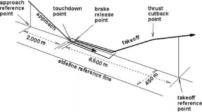
Figure 15.2. Noise measurement points at takeoff and landing
a specified period to remain in operation. In 1977, the FAA introduced noise-level standards in three tiers, as follows:
Stage I: Intended for older aircraft already flying and soon to be phased out (e.g., the B707 and DC8). These are the noisiest aircraft but least penalized because they are soon to be grounded.
Stage II: Intended for recently manufactured aircraft that have a longer lifespan (e.g., the B737 and DC9). These aircraft are noisy but must be modified to a quieter standard than Stage I. If they are to continue operating, then further modifications are necessary to bring the noise level to the Stage III standard.
Stage III: Intended for new designs with the quietest standards.
Stage IV: Further increased stringency was applied for new aircraft certification during 2006.
ICAO standards are in Annexure 16, Volume I, in Chapters 2 through 10, with each chapter addressing different aircraft classes. This book is concerned with Chapters 3 and 10, which are basically intended for new aircraft (i.e., first flight of a jet aircraft after October 6, 1977, and a propeller-driven aircraft after November 17, 1988).
To certify an aircraft’s airworthiness, there are three measuring points in an airport vicinity to ensure that the neighborhood is within the specified noise limits. Figure 15.2 shows the distances involved in locating the measuring points, which are as follows:
1.Takeoff reference point: 6,500 m (3.5 nm) from the brake release (i.e., starting) point and at an altitude given in Table 15.1.
2.Approach reference point: 2,000 m (1.08 nm) before the touchdown point, which should be within 300 m of the runway threshold line and maintained at least at a 3-deg glide slope with an aircraft at least at a 120-m altitude.
3.Sideline reference point: 450 m (0.25 nm) from the runway centerline. At the sideline, several measuring points are located along the runway. It is measured on both sides of the runway.