

12.6 Inherent Aircraft Motions as Characteristics of Design |
403 |
separately for the H-tail and the V-tail. Statistics for aircraft using FBW are included in the figure. It is advised that readers create separate plots to generate their own aircraft statistics for the particular aircraft class in which they are interested to obtain an appropriate average value.
For civil aircraft designs, the typical H-tail area is about a quarter of the wing reference area. The V-tail area varies from 12% of the wing reference area, SW, for large, long aircraft to 20% for smaller, short aircraft. There may be minor changes in empennage sizing when more detailed analyses are carried out in Phase 2 of the design.
Military aircraft require more control authority for greater maneuverability and they have shorter tail arms that require larger tail areas. The H-tail area is typically about 30 to 40% of the wing reference area. The V-tail area varies from 20 to 25% of the wing reference area. Supersonic aircraft have a movable tail for control. If a V-tail is too large, then it is divided in two halves.
Modern aircraft with FBW technology can operate with more relaxed stability margins, especially for military aircraft designs; therefore, they require smaller empennage areas compared to older conventional designs (see Figure 12.18).
In this book, trim surfaces are earmarked and not sized. Designers must ensure that there is adequate trim authority (i.e., the trim should not run out) in any condition. This is typically accomplished in Phase 2 after the configuration is finalized.
12.6 Inherent Aircraft Motions as Characteristics of Design
Once an aircraft is built, its flying qualities are the result of the effects of its mass (i.e., inertia), CG location, static margin, wing geometry, empennage areas, and control areas. Flying qualities are based on a pilot’s assessment of how an aircraft behaves under applied forces and moments. The level of ease or difficulty in controlling an aircraft is a subjective assessment by a pilot. In a marginal situation, recorded test data may satisfy airworthiness regulations yet may not prove satisfactory to the pilot. Typically, several pilots evaluate aircraft flying qualities to resolve any debatable points.
It is important that the design maintain flying qualities within preferred levels by shaping the aircraft appropriately. Whereas theoretical analyses help to minimize discrepancies, flying qualities can be determined only by actual flight tests. Like any other system analysis, control characteristics are rarely amenable to the precise theory due to a lack of exact information about the system. Therefore, accurate design information is required to make predictions with minimal error. It is cost-intensive to generate accurate design information, such as the related design coefficients and derivatives required to make theoretical analyses, which are conducted more intensively during Phase 2 of a project. Practically all modern aircraft incorporate active control technology (ACT) to improve flying qualities. This is a routine design exercise and provides considerable advantage in overcoming any undesirable behavior, which is automatically and continuously corrected.
Described herein are six important flight dynamics of particular design interest. They are based on fixed responses associated with small disturbances, making
404 |
Stability Considerations Affecting Aircraft Configuration |
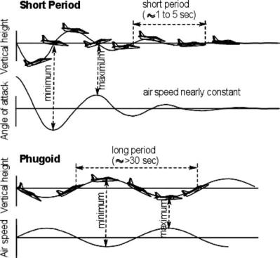
Figure 12.12. Short-period oscillations and phugoid motion
the rigid-body aircraft motion linearized. Military aircraft have additional considerations as a result of nonlinear, hard maneuvers, which are discussed in Section 12.9. The six flight dynamics are as follows:
short-period oscillation
phugoid motion (long-period oscillation)
Dutch roll
slow spiral
roll subsidence
spin
12.6.1 Short-Period Oscillation and Phugoid Motion
The diagrams in Figure 12.12 show an exaggerated aircraft flight path (i.e., altitude changes in the pitch plane). In the pitch plane, there are two different types of aircraft dynamics that result from the damping experienced when an aircraft has a small perturbation. The two longitudinal modes of motion are as follows:
1.Short-period oscillation (SPO) is associated with pitch change (α change) in which the H-tail plane acts as a powerful damper (see Figure 12.1). If a disturbance (e.g., a sharp flick of the elevator and return) causes the aircraft to enter this mode, then recovery is also quick for a stable aircraft. The H-tail acts
406 |
Stability Considerations Affecting Aircraft Configuration |
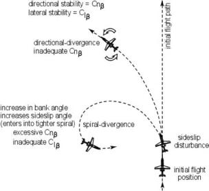
Figure 12.13. Spiral mode of motion showing divergence
12.6.2 Directional and Lateral Modes of Motion
Aircraft motion in the directional (i.e., yaw) and the lateral (i.e., roll) planes is coupled with sideslip and roll; therefore, it is convenient to address the lateral and directional stability together. These modes of motion are relatively complex in nature. FAR 23, Sections 23–143 to 23.181, address airworthiness aspects of these modes of motion. Spinning is perceived as a post-stall phenomenon and is discussed separately in Section 12.7.
The four typical modes of motion are (1) directional divergence, (2) spiral, (3) Dutch roll, and (4) roll subsidence. The limiting situation of directional and lateral stability produces two types of motion. When yaw stability is less than roll stability, the aircraft can enter directional divergence. When roll stability is less than yaw stability, the aircraft can enter spiral divergence. Figure 12.13 shows the two extremes of directional and spiral divergence. The Dutch roll occurs along the straight initial path, as shown in Figure 12.14.
The wing acts as a strong damper to the roll motion; its extent depends on the wing aspect ratio. A large V-tail is a strong damper to the yaw motion. It is important to understand the role of damping in stability. When configuring an aircraft, designers need to optimize the relationship between the wing and V-tail geometries. The four modes of motion are as follows:
1.Directional Divergence. This results from directional (i.e, yaw) instability. The fuselage is a destabilizing body, and if an aircraft does not have a sufficiently large V-tail to provide stability, then sideslip increases accompanied by some roll, with the extent depending on the roll stability. The condition can continue until the aircraft is broadside to the relative wind, as shown in Figure 12.13.
2.Spiral. However, if the aircraft has a large V-tail with a high degree of directional (i.e., yaw) stability but is not very stable laterally (i.e., roll) (e.g., a lowwing aircraft with no dihedral or sweep), then the aircraft banks as a result of rolling while sideslipping.
12.6 Inherent Aircraft Motions as Characteristics of Design |
407 |
Figure 12.14. Dutch roll motion
This is a nonoscillatory motion with characteristics that are determined by the balance of directional and lateral stability. In this case, when an aircraft is in a bank and sideslipping, the side force tends to turn the plane into the relative wind. However, the outer wing is traveling faster, generating more lift, and the aircraft rolls to a still higher bank angle. If poor lateral stability is available to negate the roll, the bank angle increases and the aircraft continues to turn into the sideslip in an ever-increasing (i.e., tighter) steeper spiral, which is spiral divergence (see Figure 12.13). In other words, spiral divergence is strongly affected by Clr.
The initiation of a spiral is typically very slow and is known as a slow spiral. The time taken to double the amplitude from the initial state is long – 20 s or more. The slow buildup of a spiral-mode motion can cause high bank angles before a pilot notices an increase in the g-force. If a pilot does not notice the change in horizon, this motion may become dangerous. Night-flying without proper experience in instrument-flying has cost many lives due to spiral divergence. Trained pilots should not experience the spiral mode as dangerous – they would have adequate time to initiate recovery actions. A 747 has a nonoscillatory spiral mode that damps to half amplitude in 95 s under typical conditions; many other aircraft have unstable spiral modes that require occassional pilot input to maintain a proper heading.
3.Dutch Roll. A dutch roll is a combination of yawing and rolling motions, as shown in Figure 12.14. It can happen at any speed, developing from the use of the stick (i.e., aileron) and rudder, which generate a rolling action when in yaw. If a sideslip disturbance occurs, the aircraft yaws in one direction and, with strong roll stability, then rolls away in a countermotion. The aircraft “wags its tail” from side to side, so to speak. The term Dutch roll derives from the rhythmic motion of Dutch iceskaters swinging their arms and bodies from side to side as they skate over wide frozen areas.
When an aircraft is disturbed in yaw, the V-tail performs a role analogous to the H-tail in SPO; that is, it generates both a restoring moment proportional to the yaw angle and a resisting, damping moment proportional to the rate of yaw. Thus, one component of the Dutch roll is a damped oscillation in yaw. However, lateral stability responds to the yaw angle and the yaw rate by rolling the wings of the aircraft. Hence, the second component of a Dutch roll is an