


320 |
Aircraft Power Plant and Integration |
flying below Mach 0.5 is not preferred – it is better to use a propeller-driven aircraft flying at or below Mach 0.5.
overall efficiency, ηo = |
useful work done on airplane |
= |
WA |
= ηt × ηp |
|||
heat energy of (air |
+ |
fuel) |
Q |
||||
|
(Ve − V∞)V∞ |
|
|
|
|
|
|
= |
|
|
|
|
|
(10.5) |
|
q2−3 |
|
|
|
|
|
||
It can be shown (see [2] through [4]) that, ideally, for nonafterburning engines, the best overall efficiency, ηo, is when the engine-exhaust velocity, Ve, is twice the aircraft velocity, V∞. Bypassed turbofans provide this efficiency at high-subsonic aircraft speeds.
10.4 Introduction: Air-Breathing Aircraft Engine Types
This section describes various types of gas turbines and introduces piston engines. Aircraft propulsion depends on the extent of thrust produced by the engine. Section 10.11 presents the thrust and power available from various types of engines. Statistics for various types of aircraft engines are previous at the end of this chapter. Gas turbine sizes are progressing in making engines both larger and smaller than current sizes – that is, expanding the application envelope.
10.4.1 Simple Straight-Through Turbojet
The most elementary form of a gas turbine engine is a simple straight-through turbojet, shown schematically in Figure 10.4. In this case, the intake airflow goes straight through the entire length of the engine and exits at a higher velocity and temperature after the processes of compression, combustion, and expansion. This type of engine burns like a stove in a pressurized environment. Readers may note the “waisting” of the airflow passage as a result of the compressor reducing the volume as the turbine expands. Typically, at the LRC condition, the free-stream tube located far upstream is narrower in diameter than at the compressor face. As a result, airflow ahead of the intake plane slows down during the precompression phase.
Components associated with the thermodynamic processes within the engine have assigned station numbers, as listed in Table 10.3. (A bare engine does not have an intake and exhaust nozzle.)
Figure 10.4. A simple straight-through turbojet (pod-mounted)

10.4 Introduction: Air-Breathing Aircraft Engine Types |
321 |
||
Table 10.3. Gas turbine station number |
|
||
|
|
|
|
|
|
|
|
Number |
Station |
Description |
|
|
|
|
|
∞ |
Free Stream |
Far upstream (if precompression is ignored, then it is the same as 0) |
|
0–1 |
Intake |
A short divergent duct as a diffuser to compress inhaled airmass |
|
1–2 |
Compressor |
Active compression to increase pressure; temperature rises |
|
2–3 |
Burner |
Fuel is burned to release the heat energy |
|
3–4 |
Turbine |
Extracts the power from heat energy to drive the compressor |
|
4–5 |
Nozzle |
Generally convergent to increase flow velocity |
|
e |
|
(Station 5 is also known as e, representing the exit plane) |
|
Note:
The burner is also known as the combustion chamber (CC) and the nozzle as the exhaust duct.
Overall engine efficiency improves if the higher energy of the exhaust gas of a straight-through turbojet is extracted through an additional turbine, which can drive a fan in front of a compressor (i.e., for a turbofan engine) or a propeller (i.e., for a turboprop engine).
10.4.2 Turbofan: Bypass Engine
The energy extraction through the additional turbine lowers the rejected energy at the exhaust, resulting in a lower exhaust velocity, pressure, and temperature. The additional turbine drives a fan in front of the compressor. The large amount of airmass flowing through the fan provides thrust. Part of the intake airmass flow through the fan is diverted (i.e., bypassed as the cold secondary flow) around the engine core and does not burn. The primary flow flows through the combustion chamber and is known also as the core flow or hot flow. Figure 10.5 is a schematic diagram of a turbofan engine (the top of the figure is a bare PW 4000). The lower exhaust velocity reduces engine noise. At the design point (i.e., LRC), the lower exhaust pressure permits the nozzle exit area to be sized to make the exit pressure equal to the ambient pressure (i.e., in a perfectly expanded nozzle). This is unlike simple turbojets, which can have a higher exit pressure.
Readers should note that the component-station-numbering system follows the same pattern as for the simple straight-through turbojet. The combustion chamber in the middle maintains the same numbers (i.e., 2–3). The only difference is the fan exit, which has the subscript f. The intermediate stages of the compressor and the turbine are primed.
Typically, the BPR (see Equation 10.2) for commercial jet-aircraft turbofans (i.e., high-subsonic flight speeds of less than Mach 0.98) is around 4 to 7. Recently, turbofans for the newer Boeing787, Airbus350 and Bombardier Cseries have reached BPR of 8 to 12. For military aircraft applications (i.e., supersonic flight speeds of up to Mach 2.5), the BPR is around 1 to 3. A lower BPR keeps the fan diameter smaller and, hence, lowers the frontal drag. Multispool drive shafts offer better efficiency and response characteristics, mostly with two concentric shafts. The shaft driving the low-pressure (LP) section runs inside the hollow shaft of the highpressure (HP) section (see Figure 10.5). Three shaft turbofans have been designed, but most of the current designs use a twin spool. The recent advent of a geared turbofan is indicative of better fuel efficiencies.

322 |
Aircraft Power Plant and Integration |
Figure 10.5. Schematic diagram of a pod-mounted, long-duct, two-shaft turbofan engine
A lower fan diameter compared to the propeller permits higher rotational speed and provides the scope for a thinner aerofoil section to extract better aerodynamic benefits. The higher the BPR, the better is the fuel economy. A higher BPR demands a larger fan diameter when reduction gears may be required to keep the revolutions per minute (rpm) at a desired level. Ultra-high BPR (UHBPR) turbofans approach the class of a ducted-fan, ducted-propeller, or propfan engine. This type of engine has been built, but its cost versus performance has prevented it from breaking into the market.
10.4.3 Afterburner Engine
Afterburning (AB) is another way of thrust augmentation intended exclusively for the supersonic combat aircraft category (the Concorde is the only civil aircraft that used AB). Figure 10.6 is a cutaway diagram of a modern AB engine intended for combat aircraft.
Figure 10.6. Afterburning engine

10.4 Introduction: Air-Breathing Aircraft Engine Types |
323 |
Figure 10.7. Schematic diagram of a turboprop engine
The simple straight-through turbojets have a relatively small frontal area resulting in low drag and excess air in the exhaust flow. If additional fuel can be burned in the exhaust nozzle beyond the turbine exit plane, additional thrust can be generated to propel an aircraft at a considerably higher speed and acceleration, thereby also possibly improving propulsive efficiency. However, the reason for using AB arises from the mission demand, such as at takeoff with a high payload and acceleration to engage or disengage during combat and evasion maneuvers. Mission demand overrides the fact that there is a high level of energy rejection in the high exhaust velocity. Fuel economy degrades with AB – it takes 80 to 120% more fuel burn to gain a 30 to 50% increase in thrust. Currently, most supersonic aircraft engines have some BPR when AB is done in the cooler mixed flow past the turbine section of the primary flow.
10.4.4 Turboprop Engine
Lower-speed aircraft can use propellers for thrust generation. Therefore, instead of driving a smaller encased fan (i.e., turbofan), a large propeller (i.e., turboprop) can be driven by a gas turbine engine to improve efficiency because the exhaust energy can be further extracted to a very low exhaust velocity (i.e., nearly zero nozzle thrust). Some residual jet thrust is left at the nozzle exit plane when it needs to be added to the propeller thrust. The nozzle thrust is converted to HP and, together with the SHP generated, it becomes the equivalent SHP (ESHP).
However, a large propeller diameter limits rotational speed due to both aerodynamic (i.e., transonic blade tips) and structural (i.e., centrifugal force) considerations. Heavy reduction gears are required to reduce the propeller rpm to a desirable level. Propeller efficiency decreases when aircraft are operating at flight speeds above Mach 0.5. For shorter-range flights, a turboprop’s slower speed does not become time-critical to the users, yet it offers better fuel economy. Figure 10.7 is a schematic diagram of a typical turboprop engine. Modern turboprops have up to eight blades (see Figure 10.31), which allow a reduction of the diameter size and operate at a relatively higher rpm and aircraft speed.
10.4.5 Piston Engine
Most aircraft piston engines are the reciprocating type (i.e., positive displacement, intermittent combustion): The smaller ones have an air-cooled, two-stroke cycle; the
324 |
Aircraft Power Plant and Integration |
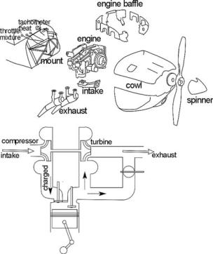
Figure 10.8. Aircraft piston engine with installation components
larger ones (typically, more than 200 HP) have a liquid-cooled, four-stroke cycle. There are a few rotary-type positive-displacement engines (e.g., Wankel) – attractive in principle but they have sealing problems. Cost-wise, rotary-type positivedisplacement engines are not yet popular; cost will decrease with increased production. Figure 10.8 shows an aircraft piston engine with installation components.
To improve high-altitude performance (with low air density), supercharging is used. Figure 10.8 shows a vane-supercharging type for precompression. Also, AVGAS differs slightly from MOGAS. Recently, some engines for the homebuilt category have been allowed to use MOGAS. Recently for small aircraft application, diesel fuel-powered piston engines have appeared in the market.
Piston engines are the oldest type used for powering aircraft. Over the life cycle of an aircraft, gas turbines are more cost effective for engine sizes of more than 500 HP. Currently, general-aviation aircraft are the main users of piston engines. Small recreational aircraft invariably are powered by piston engines.
10.5 Simplified Representation of the Gas Turbine Cycle
Figure 10.9a depicts a standard schematic diagram representing a simple straightthrough turbojet engine, as shown in Figure 10.4, with appropriate station numbers. The thermodynamic cycle associated with gas turbines is known as the Joule cycle (also known as the Brayton cycle). Figure 10.9b is the corresponding temperature– entropy diagram of an ideal Joule cycle in which compression and expansion take place isentropically.
Real engine processes are not isentropic and losses are involved associated with increased entropy. Figure 10.10 is a comparison of real and ideal cycles.