

10.2 Background |
315 |
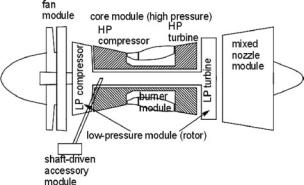
Figure 10.1. Modular concept of gas turbine design
Section 10.7: |
Considerations for engine installation |
Section 10.8: |
Intake and nozzle design |
Section 10.9: |
Nozzle and thrust reversers |
Section 10.10: |
Propeller |
Section 10.11: |
Engine-performance data |
10.1.2 Coursework Content
This chapter creates engine-performance graphs that are used in Chapter 11 for aircraft-performance analysis. In this chapter, readers generate thrust and fuel-flow levels for matched engines at various power settings, speeds, and altitudes, all in a standard atmosphere.
10.2 Background
Gliders were flying long before the Wright brothers first flew, but an engine could not be installed even when automobile piston engines became available – they were too heavy for gliders. The Wright brothers made their own lightweight gasoline engine with the help of Glenn H. Curtiss. Until World War II, aircraft were designed around available engines. Aircraft sizing was a problem – it was not optimized for the mission role but rather based on the number and/or the size of the engine installed.
During the late 1930s, Frank Whittle in the United Kingdom (who died in England in 1996) and Hans von Ohain in Germany (who died in the United States in 1998) were working independently and simultaneously on reaction-type engines using vane–blade-type precompression before combustion. Their efforts resulted in today’s gas turbine engines; however, at the time, it was difficult for Whittle to convince his peers. By the end of World War II, gas-turbine–powered jet aircraft were in operation.
Post–World War II research led to the rapid advancement of gas turbine development such that from a core gas-generator module, a family of engines can be designed using a modular concept (Figure 10.1); this allowed engine designers to offer engines as specified by aircraft designers. Similar laws in thermodynamicdesign parameters permitted power plants to be scaled (i.e., rubberized) to the requisite size around the core gas-generator module to meet the demands of the
316 |
Aircraft Power Plant and Integration |
mission requirements. The size and characteristics of an engine are determined by matching them with the aircraft mission. It is now possible for both the aircraft and the engine to be sized to the mission role, thereby improving operational economics. Modular engine design also favors low downtime for maintenance.
The potential energy locked in fuel is released through combustion. In gasturbine technology, the high energy of the combustion product can be used in two ways: (1) converted to an increase in the kinetic energy of the exhaust to produce the reactionary thrust (i.e., turbojet and turbofan); or (2) further extracted through an additional turbine to drive a propeller (i.e., turboprop) to generate thrust.
Initially, reactionary-type engines were simple straight-through airflow turbojets (see Figure 10.4). Subsequently, turbojet development improved with the addition of a fan (i.e., long compressor blades that are visible from the outside) in front of the compressor; this is called a turbofan. The intake airmass flow is split into two streams (see Figure 10.5): the core airmass flow passes through the engine as primary flow and is made to burn; the secondary flow through the fan is bypassed (hence, also called the bypass engine) around the engine and remains as cold flow. For this reason, the primary flow is known as hot flow and the secondary bypassed flow is known as cold flow.
Significant general progress has been made in the aircraft power plant design. Engine technology is substantially more complex than aircraft technology. A gasturbine operating environment demands more aerodynamic considerations than an aircraft. Stringent design considerations must accommodate very high stress levels on an engine at elevated temperatures, yet it must be as lightweight as possible. The manufacture of gas turbine parts is also a difficult task – a tough material must be machined in a complex 3D shape to a tight tolerance level. These considerations make gas turbine design a complex technology and requires an involved microprocessor-based management.
Gas turbine engines have a wide range of applications, from land-based, large prime movers for power generation and ships (both civil and military) to weightcritical airborne applications. The theory behind all the types has a common base; however, the hardware design differs, driven by the application requirements and technology level adopted. For example, land-based engines are not weight-critical and do not need to stand alone; therefore, they are less constrained in design. Surface-based gas turbines must run economically for days and/or months, generating significant power compared to standalone, lightweight aircraft engines that run for hours on varying power, altitude, g-load, and airflow demands. Even the largest aircraft gas turbine engines are small compared to land-based engines.
The success of a new gas turbine design is achieved by fully understanding and appreciating previous designs. Progress is made in increments by incorporating proven, newer technologies that emerge in the interim. Gas turbine development has a long gestation period compared to aircraft and it depends on previous designs. Typically, a technology demonstrator leads the way in introducing a new design.
Gas turbine designs have advanced to incorporate sophisticated micro- processor-based control systems with automation, which are called full authority digital electronic control (FADEC) and work in conjunction with the FBW control of aircraft. CAD, CAM, CFD, and FEM are now the standard tools for engine design.
10.2 Background |
317 |
Chart 10.1. Classification of current aircraft engine types
Liquid-cooled aircraft piston engines of more than 3,000 HP have been built. However, except for a few types, they are no longer in production because they are too heavy for the power they generate; in their place, gas turbines predominate. Gas turbine engines have a better thrust-to-weight ratio. Two successful pistons were the World War II types: the Rolls Royce (RR) Merlin and the Griffon, which produced 1,000 to 1,500 HP and weighed approximately 1,500 lb dry. Also, AVGAS is considerably more expensive than aviation turbine fuel (i.e., kerosene) (AVTUR). Today, the biggest piston engine in production is approximately 500 HP. Recently, diesel-fuel piston engines (i.e., less than 250 HP) have entered the general-aviation market. In the homebuilt market, motor gasoline (MOGAS)–powered engines have been used and are approved by the certifying agencies.
Chart 10.1 classifies all types of aircraft engines in current use; this book is concerned only with the air-breathing types.
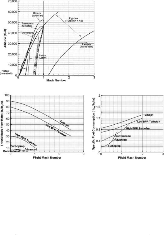
The application domains of the types addressed in this book are shown in Figure 10.2. High BPR turbofans are intended for high-subsonic speeds. At supersonic speeds, the BPR is less than 3. Typically, turboprop-powered aircraft speeds are at and below Mach 0.5. Piston-engine–powered aircraft are at the lowest end of the speed range.
Typical levels of specific thrust (F/m˙ a, lb/lb/s) and specific fuel consumption
(sfc, lb/hr/lb) of various types of gas turbine engines are shown in Figure 10.3. Table 10.1 lists various efficiencies of the different classes of aircraft engines.
Table 10.2 shows the progress made in the last half-century, indicating the advances made in engine-weight savings. Since the 1970s, compliance regarding engine-noise levels has been a requirement of the certifying agencies. Pollution levels due to noise and emissions are steadily decreasing (see Chapter 14).
If required (or preferred), the internal contours of the intake and exhaust of a civil aircraft nacelle pod are designed by engine designers in consultation with airframe designers. Shaping of the nacelle’s external contour is the responsibility of aircraft designers. Military aircraft intakes and exhausts have higher degrees of
318 |
Aircraft Power Plant and Integration |
Figure 10.2. Application domains of various types of air-breathing aircraft engines
(a) Specific Thrust |
(b) Specific Fuel Consumption |
|||
Figure 10.3. Typical performance levels of various gas turbine engines |
||||
Table 10.1. Efficiencies of engine types |
|
|
|
|
|
|
|
|
|
|
|
|
|
|
|
Thermal efficiency |
Propulsive efficiency |
Overall efficiency |
|
|
|
|
|
|
Current types |
0.60–0.65 |
0.75–0.85 |
0.50–0.55 |
|
Propfan |
0.52–0.55 |
0.80–0.85 |
0.54–0.55 |
|
Propfan (ad) |
0.52–0.55 |
0.70–0.76 |
0.46–0.50 |
|
High BPR |
0.48–0.55 |
0.62–0.68 |
0.40–0.42 |
|
Low BPR |
0.40–0.50 |
0.55–0.60 |
0.35–0.38 |
|
Turbojet |
0.40–0.45 |
0.45–0.52 |
0.28–3.20 |
|
Notes:
Advanced propfan BPR = bypass ratio

10.3 Definitions |
319 |
Table 10.2. Progress in jet engines
|
|
Thrust/weight ratio |
|
|
|
1950s |
(J69 class) |
2.8–3.2 |
1960s |
(JT8D, JT3D class) |
3.2–3.6 |
1970s |
(J79 class) |
4.5–5.0 |
1980s |
(TF34 class) |
6.0–6.5 |
1990s |
(F100, F404 class) |
0.5–8.0 |
Current |
8.0–9.0 |
|
|
|
|
complexity and are design-specific. Military aircraft intake and exhaust ducts are developed by aircraft designers in consultation with engine designers.
10.3 Definitions
This section defines various terms used in jet-engine performance analysis. References [3] through [6] may be consulted for derivations of the expressions.
SFC: The fuel-flow rate required to produce one unit of thrust, or shaft horsepower (SHP):
SFC = (fuel flow rate)/(thrust or power) |
(10.1) |
Units of SFC are in lb/hr per pound of thrust produced (in SI units, gm/s/N) – the lower the better. More precisely, reaction-type engines use TSFC and propellerdriven engines use PSFC, where T and P denote thrust and power, respectively.
For turbofan engines (see Section 10.4.2):
secondary airmass flow over the core engine |
= m˙ s /m˙ p |
|
BPR = primary airmass flow through the core (combustion) |
(10.2) |
Following are the definitions of various types of jet engine efficiencies. The subscripts indicate the gas turbine component station numbers, as shown in Figure 10.4 (in the figure, 5 represents e).
thermal efficiency, ηt = |
mechanical energy produced by the engine |
= |
WE |
heat energy of (air + fuel) |
Q |
= |
Ve2 − V∞2 |
|
1 |
− |
PR |
2Cp(T3 − T2) = |
|
|
1−γ
γ |
(10.3) |
For a particular aircraft speed, V∞, the higher the exhaust velocity Ve, the better is the ηt of the engine. Heat addition at the combustion chamber, q2−3 = Cp(T3 −
T1) ≈ Cp(Tt3 − Tt1).
propulsive efficiency, ηp = |
|
|
useful work done on airplane |
|
||
mechanical energy produced by the engine |
|
|||||
= |
|
WA |
= |
2V∞ |
(10.4) |
|
|
WE |
Ve + V∞ |
|
|||
For subsonic aircraft, Ve V∞. Clearly, for a given engine exhaust velocity, Ve, the higher the aircraft speed, the better is the propulsion efficiency, ηp. A jet aircraft