


282 |
Aircraft Drag |
databank to generate semi-empirically the CDw graph during the conceptual design phase. Today, CFD can generate wave drag accurately and is an indispensable tool (see Chapter 14), replacing the empirical/semi-empirical approach. CFD analysis is beyond the scope of this book. It is suggested that practitioners use data from tests or from CFD analysis in conjunction with an empirical approach.
9.13 Total Aircraft Drag
Total aircraft drag is the sum of all drags estimated in Sections 9.8 through 9.12, as follows for LRC and HSC:
At LRC,
|
C2 |
|
CD = CDpmin + CDp + |
L |
(9.30) |
π AR |
At HSC,
C2
(Mcrit)CD = CDpmin + CDp + L + CDw (9.31)
π AR
At takeoff and landing, additional drag exists, as explained in the next section.
9.14 Low-Speed Aircraft Drag at Takeoff and Landing
For safety in operation and aircraft structural integrity, aircraft speed at takeoff and landing must be kept as low as possible. At ground proximity, lower speed would provide longer reaction time for the pilot, easing the task of controlling an aircraft at a precise speed. Keeping an aircraft aloft at low speed is achieved by increasing lift through increasing wing camber and area using high-lift devices such as a flap and/or a slat. Deployment of a flap and slat increases drag; the extent depends on the type and degree of deflection. Of course, in this scenario, the undercarriage remains extended, which also would incur a substantial drag increase. At approach to landing, especially for military aircraft, it may require “washing out” of speed to slow down by using fuselage-mounted speed brakes (in the case of civil aircraft, this is accomplished by wing-mounted spoilers). Extension of all these items is known as a dirty configuration of the aircraft, as opposed to a clean configuration at cruise. Deployment of these devices is speed-limited in order to maintain structural integrity; that is, a certain speed for each type of device extension should not be exceeded.
After takeoff, at a safe altitude of 200 ft, pilots typically retract the undercarriage, resulting in noticeable acceleration and gain in speed. At about an 800-ft altitude with appropriate speed gain, the pilot retracts the high-lift devices. The aircraft is then in the clean configuration, ready for an enroute climb to cruise altitude; therefore, this is sometimes known as enroute configuration or cruise configuration.
9.14.1 High-Lift Device Drag
High-lift devices are typically flaps and slats, which can be deployed independently of each other. Some aircraft have flaps but no slats. Flaps and slats conform to the
9.14 Low-Speed Aircraft Drag at Takeoff and Landing |
283 |
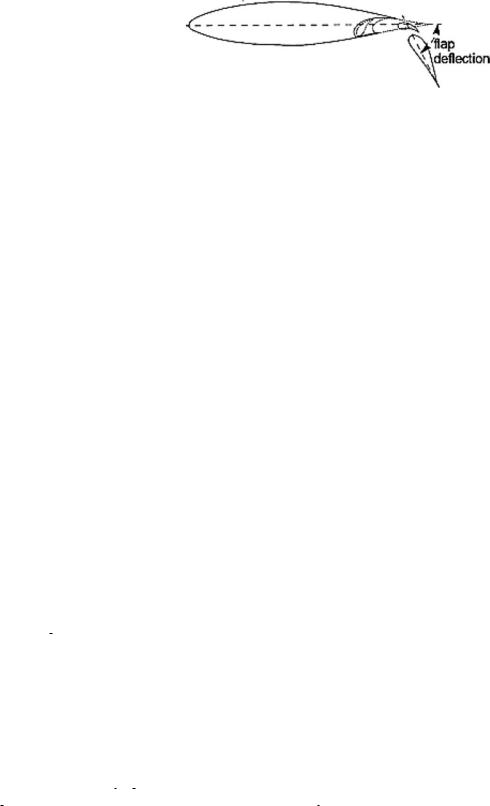
Figure 9.9. NACA 632–118 aerofoil
aerofoil shape in the retracted position (see Section 3.10). The function of a high-lift device is to increase the aerofoil camber when it is deflected relative to the baseline aerofoil. If it extends beyond the wing LE and trailing edge, then the wing area is increased. A camber increase causes an increase in lift for the same angle of attack at the expense of drag increase. Slats are nearly full span, but flaps can be anywhere from part to full span (i.e., flaperon). Typically, flaps are sized up to about two thirds from the wing root. The flap-chord-to-aerofoil-chord (cc/c) ratio is in the order of 0.2 to 0.3. The main contribution to drag from high-lift devices is proportional to their projected area normal to free-stream air. The associated parameters affecting drag contributions are as follows:
type of flap or slat (see Section 3.10)
extent of flap or slat chord to aerofoil chord (typically, flap has 20 to 30% of wing chord)
extent of deflection (flap at takeoff is from 7 to 15 deg; at landing, it is from 25 to 60 deg)
gaps between the wing and flap or slat (depends on the construction)
extent of flap or slat span
fuselage width fraction of wing span
wing sweep, t/c, twist, and AR
The myriad variables make formulation of semi-empirical relations difficult. References [1], [4], and [5] offer different methodologies. It is recommended that practitioners use CFD and test data. Reference [14] gives detailed test results of a double-slotted flap (0.309c) NACA 632–118 aerofoil (Figure 9.9). Both elements of a double-slotted flap move together, and the deflection of the last element is the overall deflection. For wing application, this requires an aspect-ratio correction, as described in Section 3.13.
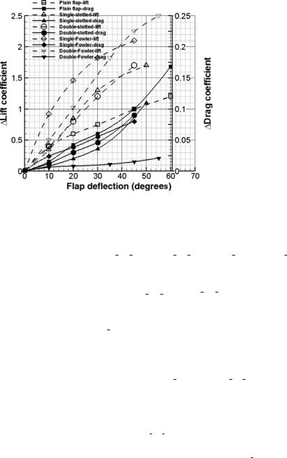
Figure 9.10 is generated from various sources giving averaged typical values ofCL and CD flap versus flap deflection. It does not represent any particular aerofoil and is intended only for coursework to be familiar with the order of magnitude involved without loss of overall accuracy. The methodology is approximate; practicing engineers should use data generated by tests and CFD.
The simple semi-empirical relation for flap drag given in Equation 9.32 is generated from flap-drag data shown in Figure 9.10. The methodology starts by working on a straight wing ( 0) with an aspect ratio of 8, flap-span-to-wing-span ratio (bf/b) of two-thirds, and a fuselage-width-to-wing-span ratio of less than one-fourth. Total flap drag on a straight wing ( 0) is seen as composed of two-dimensional parasite drag of the flap (CDp flap 2D), change in induced drag due to flap deployment ( CDi flap), and interference generated on deflection ( CDint flap). Equation 9.33 is
284 |
Aircraft Drag |
Figure 9.10. Flap drag
intended for a swept wing. The basic expressions are corrected for other geometries, as given in Equations 9.34 and 9.35.
Straight wing:
CD flap 0 = CD flap 2D + CDi flap + CDint flap |
(9.32) |
Swept wing: |
|
CD flap 1/4 = CD flap 0 × cos 1/4 |
(9.33) |
The empirical form of the second term of Equation 9.32 is given by: |
|
CDi flap = 0.025 × (8/ AR)0.3 × [(2b)/(3bf )]0.5 × ( CL)2 |
(9.34) |
where AR is the wing-aspect ratio and (bf/b) is the flap-to-wing-span ratio. |
|
The empirical form of the third term of Equation 9.32 is given by: |
|
CDint flap = k × CD flap 2D |
(9.35) |
where k is 0.1 for a single-slotted flap, 0.2 for a double-slotted flap, 0.25 to 0.3 for a single-Fowler flap, and 0.3 to 0.4 for a double-Fowler flap. Lower values may be used at lower settings.
Figure 9.10 shows the CD flap 2D for various flap types at various deflection angles with the corresponding maximum CL gain given in Table 9.1. Aircraft fly well below CLmax, keeping a safe margin. Increase CDi flap by 0.002 if the slats are deployed.
An aircraft has an aspect ratio, AR = 7.5, 1/ = 20 deg,
4
(bf/b) = 2/3, and fuselage-to-wing-span ratio less than 1/4. The flap type is a single-slotted Fowler flap and there is a slat. The aircraft has CDpmin = 0.019. Construct its drag polar.
At 20 deg deflection:
It is typical for takeoff with CL = 2.2 (approximate) but can be used at landing.
9.14 Low-Speed Aircraft Drag at Takeoff and Landing |
285 |
From Figure 9.10:
CD flap 2D = 0.045 and CL = 1.46.
From Equation 9.34:
CDi flap = 0.025 × (8/7.5)0.3 × [(2/3)/(3/2)]0.5 × (1.46)2
= 0.025 × 1.02 × 2.13 = 0.054
From Equation 9.35:
CDint flap = 0.25 × 0.045 = 0.01125;
CD flap 0 = 0.045 + 0.054 + 0.01125 = 0.11, with slat on CD highlift = 0.112
For the aircraft wing:
CD flap 1/4 = CD flap 0 × cos 0 = 0.112 × cos 20 = 0.105
Induced drag:
CDi = C2 /(π AR) = (2.2)2/(3.14 × 7.5) = 4.48/23.55 = 0.21
L
Total aircraft drag:
CD = 0.019 + 0.105 + 0.21 = 0.334
At 45 deg deflection:
It is typical for landing with CL = 2.7 (approximate).
From Figure 9.10:
CD flap 2D = 0.08 and CL = 2.1
From Equation 9.34:
CDi flap = 0.025 × (8/7.5)0.3 × [(2/3)/(3/2)]0.5 × (2.1)2
= 0.025 × 1.02 × 4.41 = 0.112
From Equation 9.34:
CDint flap = 0.3 × 0.08 = 0.024
CDp flap 0 = 0.08 + 0.112 + 0.024 = 0.216
With slat on:
CDp highlift = 0.218
For the aircraft wing:
CD flap 1/4 = CD flap 0 × cos 0 = 0.218 × cos 20 = 0.201 × 0.94 = 0.205
Induced drag:
CDi = C2 /(π AR) = (2.7)2/(3.14 × 7.5) = 7.29/23.55 = 0.31
L