CHAPTER 12. ADVANCED GUI PROGRAMMING |
622 |
g2.dispose();
Point hotSpot = new Point(12,12); Toolkit tk = Toolkit.getDefaultToolkit();
Cursor cursor = tk.createCustomCursor(image,hotSpot,"square"); setCursor(cursor);
}
12.2.3Antialiasing
To draw a geometric figure such as a line or circle, you just have to color the pixels that are part of the figure, right? Actually, there is a problem with this. Pixels are little squares. Geometric figures, on the other hand, are made of geometric points that have no size at all. Think about drawing a circle, and think about a pixel on the boundary of that circle. The infinitely thin geometric boundary of the circle cuts through the pixel. Part of the pixel lies inside the circle, part lies outside. So, when we are filling the circle with color, do we color that pixel or not? A possible solution is to color the pixel if the geometric circle covers 50% or more of the pixel. Following this procedure, however, leads to a visual defect known as aliasing. It is visible in images as a jaggedness or “staircasing” e ect along the borders of shapes. Lines that are not horizontal or vertical also have a jagged, aliased appearance. (The term “aliasing” seems to refer to the fact that many di erent geometric points map to the same pixel. If you think of the real-number coordinates of a geometric point as a “name” for the pixel that contains that point, then each pixel has many di erent names or “aliases.”)
It’s not possible to build a circle out of squares, but there is a technique that can eliminate some of the jaggedness of aliased images. The technique is called antialiasing. Antialiasing is based on transparency. The idea is simple: If 50% of a pixel is covered by the geometric figure that you are trying to draw, then color that pixel with a color that is 50% transparent. If 25% of the pixel is covered, use a color that is 75% transparent (25% opaque). If the entire pixel is covered by the figure, of course, use a color that is 100% opaque—antialiasing only a ects pixels along the boundary of the shape.
In antialiasing, the color that you are drawing with is blended with the original color of the pixel, and the amount of blending depends on the fraction of the pixel that is covered by the geometric shape. (The fraction is di cult to compute exactly, so in practice, various methods are used to approximate it.) Of course, you still don’t get a picture of the exact geometric shape, but antialiased images do tend to look better than jagged, aliased images.
For an example, look at the image in the next subsection. Antialiasing is used to draw the panels in the second and third row of the image, but it is not used in the top row. You should note the jagged appearance of the lines and rectangles in the top row. (By the way, when antialiasing is applied to a line, the line is treated as a geometric rectangle whose width is equal to the size of one pixel.)
Antialiasing is supported in Graphics2D. By default, antialiasing is turned o . If g2 is a graphics context of type Graphics2D, you can turn on antialiasing in g2 by saying:
g2.setRenderingHint(RenderingHints.KEY ANTIALIASING, RenderingHints.VALUE ANTIALIAS ON);
As you can see, this is only a “hint” that you would like to use antialiasing, and it is even possible that the hint will be ignored. However, it is likely that subsequent drawing operations in g2 will be antialiased. If you want to turn antialiasing o in g2, you can just say:
CHAPTER 12. ADVANCED GUI PROGRAMMING |
623 |
g2.setRenderingHint(RenderingHints.KEY ANTIALIASING, RenderingHints.VALUE ANTIALIAS OFF);
12.2.4Strokes and Paints
When using the Graphics class, any line that you draw will be a solid line that is one pixel thick. The Graphics2D class makes it possible to draw a much greater variety of lines. You can draw lines of any thickness, and you can draw lines that are dotted or dashed instead of solid.
An object of type Stroke contains information about how lines should be drawn, including how thick the line should be and what pattern of dashes and dots, if any, should be used. Every Graphics2D has an associated Stroke object. The default Stroke draws a solid line of thickness one. To get lines with di erent properties, you just have to install a di erent stroke into the graphics context.
Stroke is an interface, not a class. The class BasicStroke, which implements the Stroke interface, is the one that is actually used to create stroke objects. For example, to create a stroke that draws solid lines with thickness equal to 3, use:
BasicStroke line3 = new BasicStroke(3);
If g2 is of type Graphics2D, the stroke can be installed in g2 by calling its setStroke() command:
g2.setStroke(line3)
After calling this method, subsequent drawing operations will use lines that are three times as wide as the usual thickness. The thickness of a line can be given by a value of type float, not just by an int. For example, to use lines of thickness 2.5 in the graphics context g2, you can say:
g2.setStroke( new BasicStroke(2.5F) );
(Fractional widths make more sense if antialiasing is turned on.)
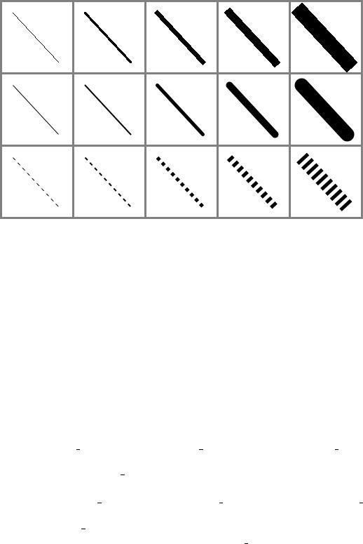
When you have a thick line, the question comes up, what to do at the ends of the line. If you draw a physical line with a large, round piece of chalk, the ends of the line will be rounded. When you draw a line on the computer screen, should the ends be rounded, or should the line simply be cut o flat? With the BasicStroke class, the choice is up to you. Maybe it’s time to look at examples. This illustration shows fifteen lines, drawn using di erent BasicStrokes. Lines in the middle row have rounded ends; lines in the other two rows are simply cut o at their endpoints. Lines of various thicknesses are shown, and the bottom row shows dashed lines. (And, as mentioned above, only the bottom two rows are antialiased.)
CHAPTER 12. ADVANCED GUI PROGRAMMING |
624 |
This illustration shows the sample program StrokeDemo.java. (You can try an applet version of the program in the on-line version of this section.) In this program, you can click and drag in any of the small panels, and the lines in all the panels will be redrawn as you move the mouse. In addition, if you right-click and drag, then rectangles will be drawn instead of lines; this shows that strokes are used for drawing the outlines of shapes and not just for straight lines. If you look at the corners of the rectangles that are drawn by the program, you’ll see that there are several ways of drawing a corner where two wide line segments meet.
All the options that you want for a BasicStroke have to be specified in the constructor. Once the stroke object is created, there is no way to change the options. There is one constructor that lets you specify all possible options:
public BasicStroke( float width, int capType, int joinType, float miterlimit, float[] dashPattern, float dashPhase )
I don’t want to cover all the options in detail, but here’s some basic info:
•width specifies the thickness of the line
•capType specifies how the ends of a line are “capped.” The possible values are
BasicStroke.CAP SQUARE, BasicStroke.CAP ROUND and BasicStroke.CAP BUTT. These values are used, respectively, in the first, second, and third rows of the above picture. The default is BasicStroke.CAP SQUARE.
•joinType specifies how two line segments are joined together at corners. Possible values are BasicStroke.JOIN MITER, BasicStroke.JOIN ROUND, and BasicStroke.JOIN BEVEL. Again, these are used in the three rows of panels in the sample program. The default is
BasicStroke.JOIN MITER.
•miterLimit is used only if the value of joinType is JOIN MITER; just use the default value,
10.0F.
•dashPattern is used to specify dotted and dashed lines. The values in the array specify lengths in the dot/dash pattern. The numbers in the array represent the length of a solid piece, followed by the length of a transparent piece, followed by the length of a solid piece,
CHAPTER 12. ADVANCED GUI PROGRAMMING |
625 |
and so on. At the end of the array, the pattern wraps back to the beginning of the array. If you want a solid line, use a di erent constructor that has fewer parameters.
•dashPhase tells the computer where to start in the dashPattern array, for the first segment of the line. Use 0 for this parameter in most cases.
For the third row in the above picture, the dashPattern is set to new float[] {5,5}. This means that the lines are drawn starting with a solid segment of length 5, followed by a transparent section of length 5, and then repeating the same pattern. A simple dotted line would have thickness 1 and dashPattern new float[] {1,1}. A pattern of short and long dashes could be made by using new float[] {10,4,4,4}. For more information, see the Java documentation, or try experimenting with the source code for the sample program.
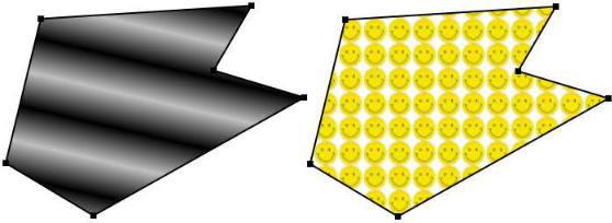
So now we can draw fancier lines. But any drawing operation is still restricted to drawing with a single color. We can get around that restriction by using Paint. An object of type Paint is used to assign color to each pixel that is “hit” by a drawing operation. Paint is an interface, and the Color class implements the Paint interface. When a color is used for painting, it applies the same color to every pixel that is hit. However, there are other types of paint where the color that is applied to a pixel depends on the coordinates of that pixel. Standard Java includes two classes that define paint with this property: GradientPaint and TexturePaint. In a gradient, the color that is applied to pixels changes gradually from one color to a second color as you move in a certain direction. In a texture, the pixel colors come from an image, which is repeated, if necessary, like a wallpaper pattern to cover the entire xy-plane.
It will be helpful to look at some examples. This illustration shows a polygon filled with two di erent textures. The polygon on the left uses a GradientPaint while the one on the right uses a TexturePaint. Note that in this picture, the paint is used only for filling the polygon. The outline of the polygon is drawn in a plain black color. However, Paint objects can be used for drawing lines as well as for filling shapes. These pictures were made by the sample program PaintDemo.java. In that program, you can select among several di erent paints, and you can control certain properties of the paints. As usual, an applet version of the program is available on line.
Gradient paints are created using the constructor
public GradientPaint(float x1, float y1, Color c1,
float x2, float y2, Color c2, boolean cyclic)