


Verilog
4. Behavioral Verilog descriptions
The behavioral Verilog supported in this version includes combinational functions, combinational and sequential tasks, and combinational and sequential always blocks.
4.1.Combinational circuits descriptions using always blocks functions and tasks
4.1.1. Combinational always blocks
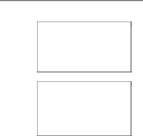
A combinational always block assigns values to output boolean functions called registers in a more sophisticated way than in the data flow style. The value assignments are made in a sequential mode. The latest assignments may cancel previous ones. An example is given in figure 24. First the register S is assigned to 0, but later on for (A & B) == 1’b1 the value for S is changed in 1’b1.
module EXAMPLE ( A, B, S); input A;
input B; output S; reg S;
always @( A or B) begin
S = 1’b0; if (A & B)
S = 1’b1;
end endmodule
Figure 24: Combinational always block
The example of figure 24 corresponds to the truth table of figure 25.
A |
B |
S |
|
|
|
|
|
|
0 |
0 |
0 |
0 |
1 |
0 |
1 |
0 |
0 |
1 |
1 |
1 |
|
|
|
Figure 25: Truth table
At the end of the always block, the truth table of the outputs signals has to be completed. Therefore an output value has to be defined for each input value. This sequential mode declaration may simplify some descriptions. In the previous example '0' is treated as a default value before specifying the value '1' for A & B == 1’b1.
A combinational always block has a sensitivity list appearing within parenthesis after the word "always @". A always block is activated if an event (value change or edge) appears on one of the sensitivity list signals. This sensitivity list contains all condition signals and any signal appearing in the left part of an assignment. In the
Verilog - 13
Verilog
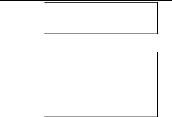
example of figure 26, the sensitivity list contains three signals which are the A, B and ADD_SUB signals. Figure 26 and figure 27 give two examples of combinational always blocks.
module ADD_SUB ( A, B, ADD_SUB, S); input [3:0] A, B;
input ADD_SUB; output [3:0] S; reg [3:0] S;
always @( A or B or ADD_SUB) if (ADD_SUB)
S = A + B;
else
S = A - B;
endmodule
Figure 26: Combinational always block
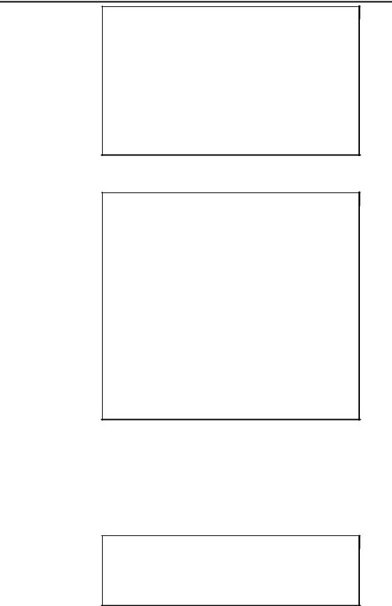
module EXAMPLE ( A, B, S); input A, B;
output S; reg S, X, Y;
always @( A or B) begin
X= A & B;
Y= B & A; if (X == Y)
S = 1’b1;
end endmodule
Figure 27: Combinational always block
Some examples described above by "Data flow Verilog descriptions", will be described again by always blocks.
4.1.2. Truth tables
The truth table of figure 28 is recalled using the data flow style in figure 29 and for comparison using the behavioral style in figure 30. The conditional assignment in figure 29 is replaced by an if statement within a always block in figure 30.
A |
B |
S |
|
|
|
|
|
|
0 |
0 |
1 |
0 |
1 |
1 |
1 |
0 |
0 |
1 |
1 |
1 |
|
|
|
8: Truth table
Verilog - 14
Verilog
module EXAMPLE ( A, B, S); input A, B;
output S;
assign S = ((A == 1’b1) && (B == 1’b0)) ? 1’b0 : 1’b1; endmodule
Figure 29 : Data flow description of a truth table
module EXAMPLE ( A, B, S); input A, B;
output S; reg S;
always @( A or B) begin
if ((A == 1’b1) && (B == 1’b0)) S = 1’b0;
else
S = 1’b1;
end endmodule
Figure 30: Behavioral description of a truth table
Similarly don't care values are supported in behavioral style. The truth table of figure 31 is described using the data flow style in figure 32 and using the behavioral style in figure 33. The selected assignment in figure 32 is replaced by a case statement within a always block in figure 33.
A |
B |
C |
S |
|
|
|
|
|
|
|
|
0 |
0 |
0 |
1 |
0 |
0 |
1 |
1 |
0 |
1 |
0 |
1 |
0 |
1 |
1 |
1 |
1 |
0 |
0 |
0 |
1 |
0 |
1 |
0 |
1 |
1 |
0 |
- |
1 |
1 |
1 |
- |
|
|
|
|
Figure 31: Truth table with don't care
Verilog - 15
Verilog
module EXAMPLE ( A, B, C, S); input A, B, C;
output S; wire [2:0] S1;
assign S1 = {A, B, C};
assign S= ((S1 == 3'b000) || (S1 == 3'b001) || (S1 == 3'b010) || (S1 == 3'b011))
? 1'b1
:(((S1 == 3'b100) || (S1 == 3'b101))
?1'b0
: 1'bx);
endmodule
Figure 32: Data flow description of a truth table with don't care
module EXAMPLE ( A, B, C, S); input A, B, C;
output S; reg S;
reg [2:0] S1;
always @(A or B or C) begin
S1 = {A, B, C}; case (S1)
3'b000,
3'b001,
3'b010,
3'b011: S = 1'b1; 3'b100,
3'b101: S = 1'b0; default: S = 1'bx;
endcase
end endmodule
Figure 33: Behavioral description of a truth table with don't care
4.1.3. Netlist declaration
For netlist declaration, the always block style does not alter at all the data flow description. The always block and its sensitivity list are just put ahead. Figure 34 recalls the description of a gate netlist using the data flow style and figure 35 gives the same description using the behavioral style. The synthesized netlist stays the same.
module EXAMPLE ( A, B, C, S); input A, B, C;
output S;
assign S = (A & B) | (~C); endmodule
Figure 34: Gate netlist description using data flow style
Verilog - 16
Verilog
module EXAMPLE ( A, B, C, S); input A, B, C;
output S; reg S;
always @(A or B or C)
S = (A & B) | (~C);
endmodule
Figure 35: Gate netlist description using behavioral style
The Verilog operators supported in the section 3 : "Data flow Verilog descriptions", are also supported in always blocks with the same restrictions and the same optimizations. Please refer to section 3.2 and 3.3 of the section 3 for more details. Figure 36 recalls an example using Verilog arithmetic operator. The synthesized netlist is identical. Similarly, for the adder, the 4 types of adders may be instantiated according to the user requirement.
module EXAMPLE ( A, B, C, D, S); input [7:0] A, B, C, D;
output [7:0] S; reg [7:0] S;
always @( A or B or C or D) S = (A + B) - (C + D);
endmodule
Figure 36: Example using arithmetic operators
8
A
+
8
8
B
8
- 
 S
S
8
8
C
+
8
D
Figure 37: Synthesized netlist
Verilog - 17