


Verilog
3.2.3. Optimizations
3.2.3.1. Resource folding and minimization of the number of multiplexers
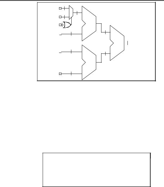
The optimizer first shares the operators and then reduces the number of required multiplexers by permuting the operands of the commutative operators. The example given in figure 15 illustrates the resource folding and the minimization of the number of multiplexers. The resulting netlist corresponding to the example described in figure 15 is shown in the figure 16. It contains 1 adder and 1 multiplexer instead of 2 adders or 1 adder and 2 multiplexers which may have been instantiated by direct reading.
module EXAMPLE ( A, B, C, E, S); input [7:0] A, B, C;
input E; output [7:0] S;
assign S = E ? A + B : C + A; endmodule
Figure 15: Example of resource folding
C |
|
|
8 |
|
|
|
8 |
|
|
|
|
|
|
|
|||||
|
|
|
|
|
|
|
|
|
|
|
|
|
|
|
|||||
B |
|
|
8 |
|
|
|
|
|
|
|
|
8 |
|
|
|||||
|
|
|
|
|
|
|
|
||||||||||||
|
|
|
|
|
|
|
|
|
|
|
|
|
|
|
|
||||
E |
|
|
|
|
|
|
|
|
+ |
|
|
S |
|||||||
|
|
|
|
|
|
|
|
||||||||||||
|
8 |
|
|
|
|
|
|
|
|
|
|
||||||||
A |
|
|
|
|
|
|
|
|
|
|
|
||||||||
|
|
|
|
|
|
|
|
|
|
|
|||||||||
|
|
|
|
|
|
|
|||||||||||||
|
|
|
|
|
|
|
|
|
|
|
|
|
|
|
|
|
|
||
|
|
|
|
|
|
|
|
|
|
|
|
|
|
|
|
|
|
|
|
|
|
|
|
|
|
|
|
|
|
|
|
|
|
|
|
|
|
|
|
Figure 16: Synthesized netlist
3.2.3.2. Recognition of common sub-expressions
The optimizer recognizes common sub-expressions. In the example of figure 17, the optimizer recognizes the sub-expression "E * F". This sub-expression is only instantiated once and the design is synthesized using only 1 multiplier as shown in figure 18. For the sub-expressions "A * C" and "C * D", the optimizer shares the multiplier and instantiates one multiplexer. The adder is also shared . The final netlist is given in figure 18 and contains 1 adder, 2 multipliers and 1 multiplexer instead of 2 adders and 4 multipliers for an unoptimized synthesis.
module EXAMPLE ( A, B, C, D, E, F, S); input [7:0] A, B, C, D, E, F;
output [15:0] S;
assign S = B ? C * D + E * F : E * F + A * C; endmodule
Figure 17: Example of standard sub-expressions
Verilog - 8
Verilog
|
8 |
A |
8 |
|
8 |
D |
|
|
8 |
B |
* |
16
8
C 

16
+ 
 S
S
8
16
E 
*
8
F
Figure 18: Synthesized netlist
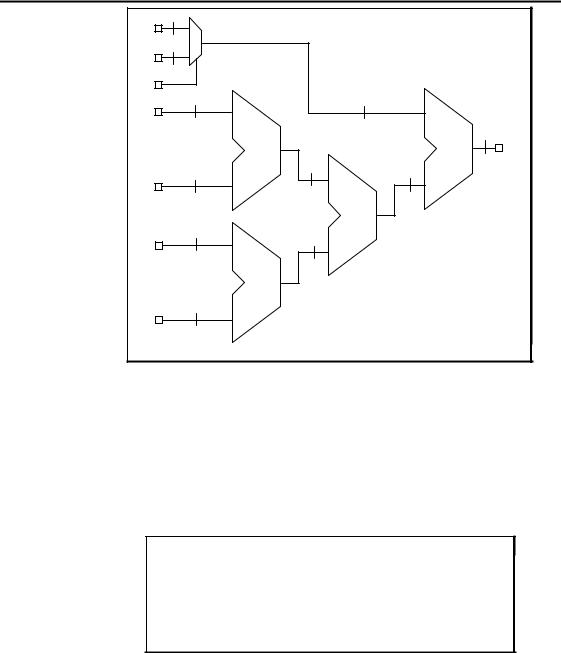
3.2.3.3. Synthesis of well-balanced trees
The optimizer synthesizes well-balanced trees if an operator has a large number of inputs. In the example of figure 19 when recognizing the sub-expression "A + B + D + E", a multiplexer is instantiated allowing to add C or F to the sub-expression according to the value of G. The final netlist given in figure 20 contains 4 adders and 1 multiplexer. For the sub-expression "A + B + D + E" the optimizer creates a well-balanced minimal depth tree of adders which is a tree of [log2 levels] as 2 input adders only exist. In the synthesized netlist, data go through at most 3 adders instead of 4 between the inputs and the output.
module EXAMPLE ( A, B, C, D, E, F, G, S); input [7:0] A, B, C, D, E, F;
input G; output [7:0] S;
assign S = G ? E + B + D + A + F : A + B + C + D + E; endmodule
Figure 19: Example of standard sub-expressions and well-balanced trees
Verilog - 9
|
|
|
|
Verilog |
8 |
|
|
|
|
F |
|
|
|
|
8 |
|
|
|
|
C |
|
|
|
|
G |
|
|
|
|
8 |
|
|
8 |
|
E |
|
|
|
|
|
|
|
|
8 |
|
+ |
|
+ |
S |
|
|
|
|
|
8 |
|
8 |
8 |
|
|
|
|
||
D |
|
|
|
|
|
|
|
+ |
|
8 |
|
8 |
|
|
B |
|
|
|
|
|
|
|
|
|
|
+ |
|
|
|
8 |
|
|
|
|
A |
|
|
|
|
Figure 20: Synthesized netlist
3.2.3.4. Expression simplification
The optimizer is able to simplify expressions. In the example given in figure 21, it replaces the expressions [A - 8'b0000_0010 * A + A] and [A- A] by 0, so it replaces the output S by 0. In the synthesized netlist, all the bits of the output signal S are connected to the ground and no adder, substracter or multiplier is instantiated.
module EXAMPLE ( A, B, S); input [7:0] A;
input B; output [7:0] S;
assign S = B ? A - A : A - 8’b0000_0010 * A + A; endmodule
Figure 21: Example of expressions which are simplified
Verilog - 10