

Broadband Packet Switching Technologies
.pdfOPTICAL INTERCONNECTION NETWORK FOR TERABIT IP ROUTERS |
319 |
|
Fig. 11.34 Hierarchy of recursive arbitration with n s pq inputs. |
||
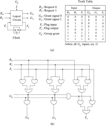
Fo , feedbacked to the input. Between |
Fo and Fi there is a D flip-flop which |
||
functions as a register forwarding |
Fo |
to Fi at the beginning of each cell time |
|
slot. When at least one of the Gg |
inputs is 0, indicating the group request of |
||
R0 |
and R1 is not granted at some upper layerŽs., we have G0 s G1 s 0, |
||
Fo |
s Fi , that is, the flag is kept unchanged in order to preserve the original |
||
preference. As shown in Figure 11.35Žb., the local grant signals have to be ANDed with the grant signals from the upper layers to provide full information whether the corresponding input is granted or not. Gg inputs are added at the final stage to allow other local logical operations to be finished in order to minimize the total arbitration time.
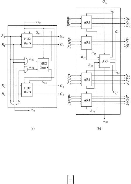
A four-input arbiter module ŽAR4. has four request signals, four output grant signals, one outgoing group request, and one incoming group grant signal. Figure 11.36Ža. depicts our design of an AR4 constructed by three AR2s Žtwo leaf AR2s and one intermediate AR2; all have the same circuitry., two two-input OR gates, and one four-input OR gate. Each leaf AR2 handles a pair of inputs and generates the local grant signals while allowing two external grant signals coming from upper layers: one from the intermediate AR2 inside the AR4, and the other from outside AR4. These two signals directly join at the AND gates at the final stage inside each leaf AR2 for minimizing the delay. Denote by Ri j and Gi j the group request signal and the
group grant signal between input i |
and input j. The intermediate |
AR2 |
||
handles the group requests Ž R01 and |
R23 . and generates the grant signals |
|||
ŽG01 and G23 . |
to each leaf AR2 respectively. It contains |
only one |
grant |
|
signal, which is |
from the upper layer for controlling the flag |
signal. |
|
|
As shown in Figure 11.36Žb., an AR16 contains five AR4s in two layers: four in the lower layer handling the local input request signals, and one in the upper layer handling the group request signals.
1 When the flag is LOW, R0 is favored; when the flag is HIGH, R1 is favored.
320 OPTICAL PACKET SWITCHES
Fig. 11.35 Ža. A two-input arbiter ŽAR2. and its truth table; Žb. its logic circuits. Ž 1999 IEEE..
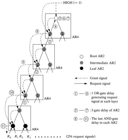
Figure 11.37 illustrates a 256-input arbiter ŽAR256. constructed from AR4s, and its arbitration delay components. The path numbered from 1 to 11 shows the delay from when an input sends its request signal till it receives the grant signal. The first four gates delays Ž1 4. constitute the time for the input’s request signal to pass though the four layers of AR4s and reach the root AR2, where one OR-gate delay is needed at each layer to generate the request signal wsee Figure 11.36Ža.x. The next three gate delays Ž5 7. constitute the time while the root AR2 performs its arbitration wsee Figure
OPTICAL INTERCONNECTION NETWORK FOR TERABIT IP ROUTERS |
321 |
Fig. 11.36 Ža. A 4-input arbiter ŽAR4. and Žb. a 16-input arbiter ŽAR16. constructed from five AR4s. Ž 1999 IEEE..
11.35Žb.x. The last four gate delays Ž8 11. constitute the time for the grant signals in the upper layers to pass down to the corresponding input. The total arbitration time of an AR256 is then 11 gate delays. It thus follows that the arbitration time ŽTn . of an n-input arbiter using such implementation is
n |
|
Ž11.1. |
Tn s 2 log4 2 |
q 3. |
11.4.5.4 Priority PPA Among the packets contending for the same output, those from real-time sessions are more delay-sensitive than the others from non-real-time sessions, so they should have higher priority. Therefore, sessions Žand thus their packets. with various QoS requirements need to be
322 OPTICAL PACKET SWITCHES
Fig. 11.37 Decomposition of arbitration delay in an AR256. Ž 1999 IEEE..
assigned different levels of service priority. Below it is shown how to enhance the PPA for handling priority.
Two priority representations are used in our design for transfer efficiency and arbitration convenience, respectively. Suppose p levels of priority are supported. An input has altogether p q 1 states Žincluding the case of no request., which can be represented by using log2Ž p q 1. bits. The interlayer request information could be transferred either in series using one line or in parallel using multiple lines, depending on the tradeoff chosen between delay and pin count complexity. The serial parallel format transformation can be realized by using shift registers.
A group of p lines is used in the second representation. At most one of them is HIGH, indicating that there is one request at the corresponding level of priority. There will be no request if all output lines are LOW.
OPTICAL INTERCONNECTION NETWORK FOR TERABIT IP ROUTERS |
323 |
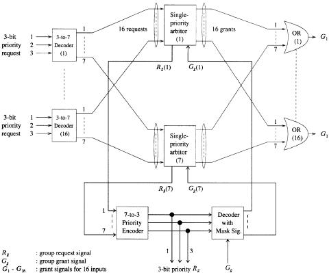
Fig. 11.38 Demonstration of priority handling with parallel arbitration: seven priority levels and 16 inputs.
Our solution to multipriority arbitration relies on a group of parallel single-priority arbiters to resolve the contention at each level of priority simultaneously. Multiple single-priority arbiters are necessary to maintain the arbitration states Žstates of the flip-flops. for each level of priority, which will be changed only when an input request at this priority level is granted. A preprocessing phase and a postprocessing phase are then added, as demonstrated in Figure 11.38, with a multipriority arbiter, which handles 16 inputs and seven levels of priority. A decoder is used at each input to decode the three-line priority request into seven single lines, each representing the request in the corresponding level of priority and entering the corresponding arbiter for single-priority contention resolution. An OR gate is used at each output to combine all corresponding local grants from the single-priority arbiters to produce the final grants for each input.
Meanwhile, every single-priority arbiter generates a group request signal for the upper layer’s arbitration; it receives a group grant signal later, which indicates if this group of requests Žat the corresponding level of priority. is granted or not. A priority encoder collects all the group requests from the
324 OPTICAL PACKET SWITCHES
single-priority arbiters and indicates among them the highest priority with its three-line output. The outputs, in addition to being forwarded to the upper layer, will also be used to inhibit the arbiters with lower priority from producing any active grants. A decoder with its outputs masked by the upper-layer grant signal is used to decompose the output of the priority encoder into seven single-line grant signals, each for a single-priority arbiter. Only the arbiter at the corresponding level of priority will receive the upper layer’s grant signal, while all the others will receive nothing but a LOW grant signal.
11.4.6OIN Complexity
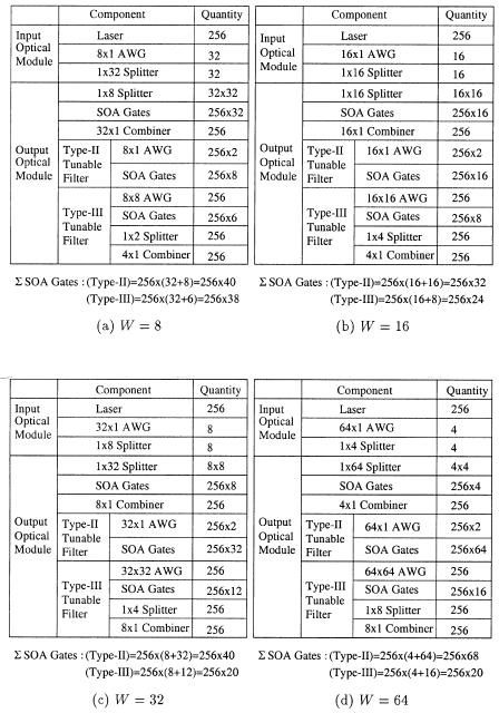
11.4.6.1 Component Complexity The complexity of the proposed 256 256 OIN is determined by the numbers of optical components and of interconnection lines between optical components and between the optical and electronic components. Figure 11.39 lists the optical components used in the OIN with different available wavelengths. The number of SOA gates dominates the component and interconnection complexity. The total number of SOA gates is equal to 256 32 when using type-II tunable filters with 16 wavelengths Ži.e., W s 16., or 256 24 when using type-III tunable filters. The component complexity of the 256 256 OIN with respect to 8, 32, and 64 wavelengths is also shown in Figure 11.39. In addition, Figure 11.39 indicates that the total number of SOA gates of the switching fabrics at the OOMs decreases as the wavelength number W increases. However, the number of SOA gates in the type-II tunable filter is proportional to the number of wavelengths. The total number of SOA gates of the OIN based on the type-II tunable filter is equal to 256 256rW q 256W, where the first term represents the number of SOA gates used in the switching fabrics and the second term represents the number of the SOA gates used in type-II tunable filters. It is also shown that the OIN with 16 wavelengths based on type-II tunable filters has the fewest SOA gates. If type-III tunable filters are applied, the OIN with W s 32 or 64 has the fewest SOA gates.
Because the on off switching of multiple wavelengths is performed at each SOA gate in the switching fabrics, the signal output of one wavelength varies according to the gain fluctuation induced by modulation of other wavelengths, even when the input power of the wavelength is constant. This is crosstalk induced by the gain saturation in the SOA gate and is often referred as cross-saturation. The impact of the cross-saturation on the performance of the OIN will become severe as the wavelength number passing through the SOA gate increases. To reduce this crosstalk in SOA gates, gain-clamped SOA gates w57x are necessary to provide a constant optical gain over a wider range of wavelength power as more wavelengths are used in the OIN
To avoid the wavelength-dependent and polarization-dependent loss experiencing in the SOA gates, electroabsorption modulators ŽEAMs. w58x can be
OPTICAL INTERCONNECTION NETWORK FOR TERABIT IP ROUTERS |
325 |
Fig. 11.39 Component complexity of 256 256 optical interconnection network with different numbers of wavelengths, W.
326 OPTICAL PACKET SWITCHES
used to perform faster switching Ž 100 ps. in multiple wavelength levels instead of the SOA gates in the proposed OIN. To compensate for the high coupling loss caused by the EAM, higher-power EDFAs or EAMs integrated with semiconductor optical amplifiers will be necessary w59x. Here, the SOA-based OIN is considered because the SOA can provide high gain and fast switching Ž 1 ns. simultaneously.
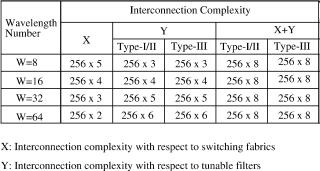
11.4.6.2 Interconnection Complexity As a representative interconnection complexity, the interconnection between the electronic controller and the 256 256 OIN is evaluated. The interconnection complexity of the proposed 256 256 OIN is determined by the number of the SOA gates in the OOMs. The types of tunable filters and the number of wavelengths applied to the OIN are two dominant factors of the interconnection complexity, because they determine the number of SOA gates in the OOMs. Because the interconnection complexity with type-I and type-II tunable filters is the same, only type-II and type-III tunable filters are considered in this regard.
Figure 11.40 shows the interconnection complexity for different wavelengths ŽW s 8, 16, 32, and 64. and different types of tunable filters, where X is the complexity introduced by the switching fabrics, Y is the complexity represented by the tunable filters, and X q Y gives the total interconnection complexity. Type-I and type-II tunable filters have the same interconnection complexity. For example, if W s 16, X s Y s 256 4 when using type-I -II, or -III tunable filters. As shown in Figure 11.40, the total interconnection complexity, X q Y, is equal to 256 8, and is independent of the wavelength number and the type of tunable filter used in the OIN.
11.4.7Power Budget Analysis
Power loss in the OIN, which is due to splitting loss, depends on the number of wavelengths and the size of the switching fabric of each OOM. To compensate for power loss in the OIN, optical amplifiers, such as EDFAs
Fig. 11.40 Interconnection complexity of the 256 256 OIN for different types of tunable filter and different wavelength numbers W.
OPTICAL INTERCONNECTION NETWORK FOR TERABIT IP ROUTERS |
327 |
and SOA gates, have to provide wide bandwidth to accommodate multiple wavelengths with uniform gain in the 1550-nm window. At each IOM, to avoid the problems introduced by direct modulation of lasers, such as large frequency chirp, an external modulator ŽEM. is used to obtain an optical on off keying ŽOOK. signal.
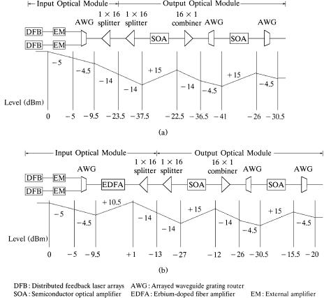
Figure 11.41 shows the optical signal path through the OIN with type-II tunable filters and W s 16. All the optical components are represented with their gains or losses. For simplicity of modeling and analysis, the OIN is assumed to be fully loaded and all the possible connections between the input output pairs established. Second, optical signals are represented by their optical power corresponding to bit mark space data signals. Third, frequency chirp due to the EM and dispersion effects of all the components are not taken into consideration since signals are transmitted only in the
Fig. 11.41 Power budget of the 256 256 optical interconnection network with 16 wavelengths and type-II tunable filters: Ža. before and Žb. after power compensation by EDFA.
328 OPTICAL PACKET SWITCHES
short-length fibers in the OIN. Finally, all the light reflections in the system are ignored and all the passive components are assumed to be polarizationinsensitive.
Figure 11.41Ža. shows that, without power compensation, the received power is only y30.5 dBm, much less than required sensitivity of about y20 dBm at the bit error rate ŽBER. of 10y12 for signals at 10 Gbitrs. To increase the received optical power, optical amplifiers are necessary to provide sufficient gain to compensate for the power loss in the OIN. In the proposed OIN, there are two kinds of optical amplifiers to perform the power compensation function. One is the SOA and the other is the EDFA. As shown in Figure 11,41Žb., an EDFA with 10.5-dB gain at each IOM is used to amplify 16 wavelengths simultaneously, so that the sensitivity at the receiver is increased to y20 dBm. Note that the gain provided by the EDFA needs to be increased to 20 dB if the AWG, which is near the output link of type-II tunable filter, is replaced by a 16 1 combiner.
11.4.8Crosstalk Analysis
In the OIN, crosstalk is caused by the finite onroff ratio Ži.e., the ratio of gain on and gain off, or GON rGOFF . of an SOA gate. More specifically,
Px, gate s Pin, gate GOFF , where Px, gate is the output power of an SOA gate in the off state, and Pin, gate is the input power of the SOA gate. Basically, crosstalk components are categorized into two types. One, referred to as
incoherent crosstalk, can be taken into account by power addition. The second type, homowa®elength crosstalk, occurs when the signal channels and their beats fall within the receiver electrical bandwidth.
The on and off states of SOAs, as switching gates, are controlled by their injection currents. An SOA in the off state Žwithout injection current. absorbs incident optical power and blocks the signal channel. However, some optical power leaks from the SOA even when it is in the off state. The power leakage becomes crosstalk when it is combined with the signal at an output port of OIN.
It is assumed that the OIN is fully loaded and packets arriving at all of its input ports are sent to their destined output ports. Only one output port of the OIN, as shown in Figure 11.42, is considered.
Figure 11.42 shows the crosstalk path in an OOM, where up to 16 WDM signals from 16 different IOMs are sent to the 16 16 switching fabric Žsee position A in the figure.. Each WDM signal can carry up to 16 different wavelengths at each output port in the switching fabric. For each output of the OOM, only one of these 16 WDM signals will be selected and delivered to the tunable filter. That is, for each output of the 16 16 switching fabric only one SOA will be turned on and the other 15 SOA gates will be turned off Žsee position B in the figure.. Thus, there is only one dominant WDM signal, and up to 15 WDM crosstalk channels are combined with it to be sent to the tunable filter at each output switch module ŽOSM. Žposition C in the figure..