

Broadband Packet Switching Technologies
.pdfOPTICAL INTERCONNECTION NETWORK FOR TERABIT IP ROUTERS |
309 |
bus is 64 bits, its frequency is 66 MHz. Simply downloading all 2 256 tables will take about 31 seconds, which is unacceptably large.
On the other hand, multiple RCs can be arranged in a hierarchical way to provide load balancing. One of the RCs can be responsible for maintaining a common RIB shared by the others in the system. Each RC will handle a number of RMs and this number depends on the processing power of the RC and the bandwidth of the interconnection Ži.e., control plane. between the RCs and the RMs. The traffic on the control plane include routing information, network control messages, FIB updates, packet filter management messages, and other local hardware monitoring and diagnosis messages.
Another challenge is to design an efficient control structure for interconnecting the RCs and the RMs. One can either separate the control plane and data plane or let both share a common plane, such as the OIN, where control traffic should have higher priority than data. The advantage of using separate planes is to reduce the complexity of switch interconnection management and to improve the data throughput performance. Besides, the router will have better scalability in that the design of control plane and data plane can be optimized separately.
11.4.4Optical Interconnection Network
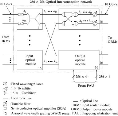
Figure 11.25 shows the proposed 256 256 OIN, which can easily provide the multicast function due to its broadcast-and-select property. The OIN consists of two kinds of optical switching modules: input optical modules ŽIOMs. and output optical modules ŽOOMs.. There are 16 of each kind in the OIN. Each IOM uses the same set of 16 different wavelengths Ž 1 to16 .; each of the 16 input links at an IOM is assigned a distinct wavelength from the set, which carries packet segments under transmission. In each time slot, up to 16 packet segments at an IOM can be multiplexed by an arrayed-waveguide grating ŽAWG. router. The multiplexed signal is then broadcast to all 16 OOMs by a passive 1 16 splitter.
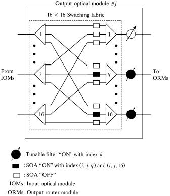
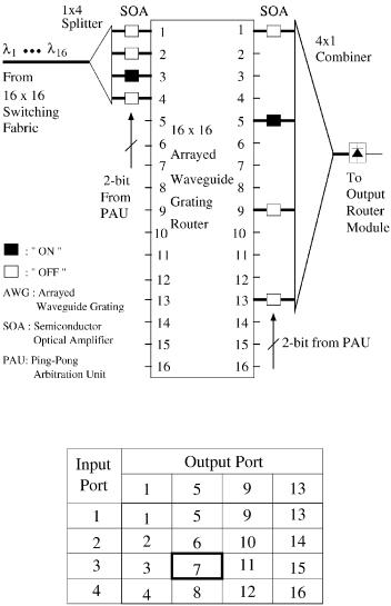
At each OOM, a 16 16 fully connected switching fabric performs the multicast switching function by properly controlling the semiconductor optical amplifier ŽSOA. gates. There are a total of 256 SOA gates in each OOM. At most 16 of them can be turned on simultaneously. The tunable filter, controlled by the PAU, is used to dynamically choose one of the 16 wavelengths in every time slot. As illustrated in Figure 11.26, it is assumed that a packet segment from the kth input link of the ith IOM is destined for the qth and 16th output links of the jth OOM, where 1 F i, j, k, q F 16. These two multicast connections are established by turning on the SOA gates with index Ži, j, q. and Ži, j, 16. only Žthe others are turned off.. The tunable filters at the qth and 16th output links of the jth OOM are turned on with index k, which is provided by the PAU.
310 OPTICAL PACKET SWITCHES
Fig. 11.25 256 256 optical interconnection network.
11.4.4.1 Input Optical Module The IOMs carry packets at 10 Gbitrs. At each IOM, distributed Bragg reflector ŽDBR. or distributed feedback ŽDFB. laser arrays can be used as the laser sources between 1525 and 1565 nm to match the gain bandwidth of commercially available EDFAs. Each EDFA can amplify multiple wavelengths simultaneously. Each input link of an IOM is connected to a laser with fixed wavelength.
To improve the chirp performance, a DFB laser diode integrated with an external modulator ŽEM. operating at 10 Gbitrs has been fabricated w52x. To ensure output power levels and chirp performance, an SOA and EMs can be integrated with the DFB laser arrays w53x. This monolithically integrated WDM source is able to provide multiwavelength capability and significantly reduce the cost per wavelength. In addition, it can also eliminate the alignment of fibers to individual lasers, reduce component count and coupling loss between components, and increase the reliability.
OPTICAL INTERCONNECTION NETWORK FOR TERABIT IP ROUTERS |
311 |
Fig. 11.26 Control in the jth output optical module.
11.4.4.2 Output Optical Module Each 16 16 switching fabric should be capable of connecting simultaneously two or more IOMs to all tunable filters at an OOM, so it needs to have broadcast capability and to be strictly nonblocking. As shown in Figure 11.26, a space switch can meet this requirement simply and can be constructed by using SOA gates.
In addition to their fast switching function Ž 1 ns., SOA gates can provide some gain to compensate the coupling loss and splitting loss caused by the splitters and combiners and the connection between discrete optical devices. Furthermore, SOA gates can be monolithically integrated with the passive couplers to enhance the reliability and loss performance between components.
11.4.4.3 Tunable Filters Tunable filters are used to perform wavelength selection in the OIN. Three possible ways to implement the tunable filter are considered here.
312 OPTICAL PACKET SWITCHES
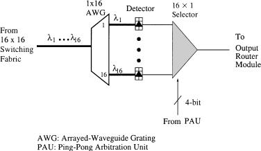
Fig. 11.27 Type-I tunable filter.
Type-I Tunable Filter: The type-I tunable filter, as shown in Figure 11.27, performs the wavelength selection in the electrical domain. Each
output of a 16 16 switching fabric is connected to a 1 16 AWG router, which is made from high-index indium phosphide ŽInP. material and is capable of demultiplexing 16 wavelengths in the 1550-nm window. Figure 11.28 shows the connectivity of a 16 16 AWG router. For
example, if the WDM signal enters the 7th input port of the AWG router, only the 14th wavelength Ž 14 . will be sent out through the 8th output port. Each demultiplexed wavelength is detected through a high-speed signal detector. Each detector has a laser waveguide structure and can be monolithically integrated with the AWG router, thus increasing the reliability and reducing the packaging cost of the AWG router. Finally, a 16 1 electronic selector is used to select the desired signal from the 16 detectors. The selector is controlled by the 4-bit
control signal from the PAU. An alternative electronic selector is the InP-based optoelectronic integrated circuit ŽOEIC. receiver array w54x,
which operates at 10 Gbitrs per channel and integrates 16 p i n photodiodes with a heterojunction bipolar transistor ŽHBT. preamplifier.
Type-II Tunable Filter: The type-II tunable filter, as shown in Figure 11.29, performs the wavelength selection optically. It has two AWGs.
The first one, 1 16, performs the demultiplexing, while the second, 16 1, performs the multiplexing. By properly controlling the SOA gates, only one of the 16 wavelengths is selected. The selected wavelength passes through the second AWG and then is converted into an electronic signal by a detector. A PLC PLC direct attachment technique w55x can be used to construct this type of tunable filter and to
OPTICAL INTERCONNECTION NETWORK FOR TERABIT IP ROUTERS |
313 |
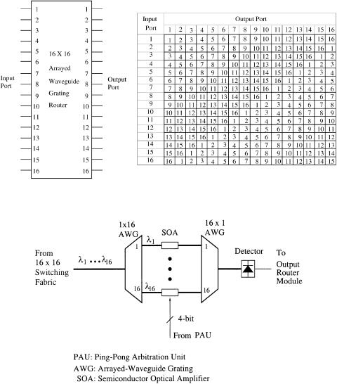
Fig. 11.28 16 16 AWG router connectivity.
Fig. 11.29 Type-II tunable filter.
integrate the AWG routers and the SOA gates. This hybrid integration of PLC and SOA gates can reduce the coupling loss and increase the reliability.
Type-III Tunable Filter: The type-III tunable filter, as shown in Figure 11.30, performs the wavelength selection optically. In contrast with the type-II filter, it uses only one 16 16 AWG router. Any one of the 16 wavelengths can be selected through its specific combination of SOA
314 OPTICAL PACKET SWITCHES
Fig. 11.30 Type-III tunable filter.
Fig. 11.31 Connectivity of type-III tunable filter.
gates at the input and output sides of the AWG router w56x. Figure 11.31 shows a way to choose any one of the 16 wavelengths. The 16 16 AWG router will route a wavelength k from input port x Ž x s 1, . . . , 16. to output port y Ž y s 1, . . . , 16., where k s Ž x q y y 1. mod 16. For example, 7 will be selected as the output by turning on the 3rd SOA gate at the input side and the 5th SOA gate at the output side of the AWG router, respectively. The number of SOA gates in the type-III tunable filter is reduced by half; only 8 SOA gates Ž4 at the input and 4
OPTICAL INTERCONNECTION NETWORK FOR TERABIT IP ROUTERS |
315 |
at the output. are used instead of 16 SOA gates in the type-II tunable filter. However, compared to type-I and type-II tunable filters, the type-III tunable filter has more power loss, caused by the 1 4 splitter and the 4 1 combiner.
11.4.5Ping-Pong Arbitration Unit
As shown in Figure 11.20, a centralized PAU is used in our router. The arbitration is pipelined with packet segment transmission in the OIN. In other words, while a HOL segment is being transmitted via the OIN, the segment next to it is also sending a request to the arbitration unit. In order to minimize the delay of forwarding multicast request signals, 256 parallel arbiters are used, each of which is associated with one output and handles 256 input request signals. The 256 incoming multicast request signals must be handled simultaneously within one time slot, that is, 51.2 ns for a 64-byte data segment sent at 10 Gbitrs.
11.4.5.1 Principles of Ping-Pong Arbitration Consider an N-input packet switch. To resolve its output contention, a solution is to use an arbiter for each output to fairly select one among those incoming packets and send back a grant signal to the corresponding input. The arbitration procedure is as follows:
1.During every arbitration cycle, each input submits a one-bit request signal to each output Žarbiter., indicating whether its packet, if any, is destined for the output.
2.Each output arbiter collects N request signals, among which one input with active request is granted according to some priority order.
3.A grant signal is sent back to acknowledge the input.
Here, the second step that arbitrates one input among N possible ones is considered.
A simple RR scheme is generally adopted in an arbiter to ensure fair arbitration among the inputs. Imagine there is a token circulating among the inputs in a certain ordering. The input that is granted by the arbiter is said to grasp the token, which represents the grant signal. The arbiter is responsible for moving the token among the inputs that have request signals. The traditional arbiters handle all inputs together, and the arbitration time is proportional to the number of inputs. As a result, the switch size or capacity is limited by the available amount of arbitration time.
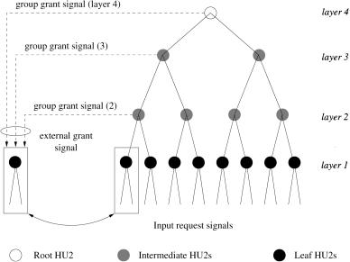
Here, it is suggested to divide the inputs into groups. Each group has its own arbiter. The request information of each group is summarized as a group request signal. Further grouping can be applied recursively to all the group request signals at the current layer, forming a tree structure, as illustrated in Figure 11.32. Thus, an arbiter with N inputs can be constructed using multiple small-size arbiters ŽARs. in each layer. Different group sizes can be used.
316 OPTICAL PACKET SWITCHES
Fig. 11.32 A tree-structured hierarchical arbitration. Ž 1999 IEEE..
Assume N s 2 k. Figure 11.32 depicts a k-layer complete binary tree with a group size of two when k s 4. Let AR2 represent a two-input AR. An AR2 contains an internal flag signal that indicates which input is favored. Once an input is granted in an arbitration cycle, the other input will be favored in the next cycle. In other words, the granted request is always chosen between left Žinput. and right alternately. That is why it is called Ping-Pong arbitration. The first layer consists of 2 ky1 arbiters called leaf AR2s. The next k y 2 layers consist of arbiters called intermediate AR2s, 2 kyi of which are in layer i. Finally, the last layer consists of only one arbiter called the root AR2.
Every AR2 has two request signals. An input request signal in layer i is the group request signal of 2 iy1 inputs and can be produced by OR gates either directly or recursively. The grant signal from an AR2 has to be fed back to all the lower-layer AR2s related to the corresponding input. Therefore, every leaf or intermediate AR2 also has an external grant signal that ANDs all grant signals at upper layers, indicating the arbitration results of upper layers. The root AR2 needs no external grant signal. At each leaf AR2, the local grant signals have to combine the arbitration results of the upper layer Ži.e., form its external grant signal. and provide full information on whether the corresponding input is granted or not.
One important use of the external grant signal is to govern the local flag signal update. If the external grant signal is invalid, which indicates that these two input requests as a whole are not granted at some upper layerŽs., then
OPTICAL INTERCONNECTION NETWORK FOR TERABIT IP ROUTERS |
317 |
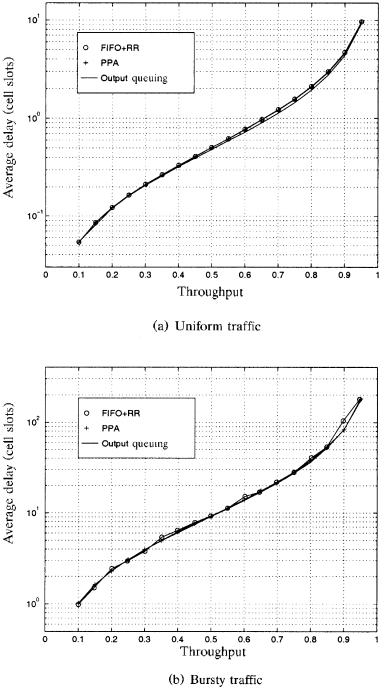
Fig. 11.33 Comparison of the PPA with FIFO q RR and output queuing: switch throughput and total average delay for a speedup factor of two.
318 OPTICAL PACKET SWITCHES
the flag should be kept unchanged in order to preserve the original preference. As shown in Figure 11.32, the external grant signal of a leaf AR2 can be added at the final stage to allow other local logical operations to be finished while waiting for the grant signals from upper layers, which minimizes the total arbitration time.
Suppose N inputs are served in increasing order of their input numbers, i.e., 1 ™2 ™ ™N ™1 under a RR scheme. Each AR2 by itself performs RR service for its two inputs. The Ping-Pong arbitration consisting of the tree of AR2s shown in Figure 11.32 can serve the inputs in the order of 1 ™3 ™2 ™4 ™1 when N s 4, for instance, which is still RR, if each input always has a packet to send and there is no conflict between any of the input request signals. Below its performance is shown by simulations.
11.4.5.2 Performance of PPA The performance of the PPA, FIFO q RR ŽFIFO for input queuing and RR for arbitration., and output queuing is compared here. A speedup factor of two is used for PPA and FIFO q RR. Simulation results are obtained from a 32 32 switch under uniform traffic Žthe output address of each segment is equally distributed among all outputs. and under bursty traffic Žon-off geometric distribution. with an average burst length of 10 segments. The bursty traffic can be used as a packet traffic model with each burst representing a packet of multiple segments destined for the same output. The output address of each packet Žburst. is also equally distributed among all outputs.
Figure 11.33 shows the throughput and total average delay of the switch under various arbitration schemes. It can be seen that the PPA performs comparably to the output queuing and the FIFO q RR. However, the output queuing is not scalable, and the RR arbitration is slower than the PPA. The overall arbitration time of the PPA for an N-input switch is proportional to log4 Nr2 when every four inputs are grouped at each layer. For instance, the PPA can reduce the arbitration time of a 256 256 switch to 11 gate delays, less than 5 ns using the current CMOS technology.
11.4.5.3 Implementation of PPA Multiple small arbiters can be recursively grouped together to form a large multilayer arbiter, as illustrated in Figure 11.32. Figure 11.34 depicts an n-input arbiter constructed by using p q-input arbiters ŽAR-q., from which the group request and grant signals are incorporated into a p-input arbiter ŽAR-p.. Constructing a 256-input arbiter starting from two-input arbiters as basic units is shown below.
Figure 11.35 shows a basic two-input arbiter ŽAR2. and its logical circuits. The AR2 contains an internally feedbacked flag signal, denoted by Fi , that indicates which input is favored.1 When all Gg inputs are 1 Žindicating that the two input requests R0 and R1 as a whole are granted by all the upper layers., once one input is granted in an arbitration cycle, the other input will be favored in the next cycle, as shown by the truth table in Figure 11.35Ža.. This mechanism is maintained by producing an output flag signal, denoted by