

What is a Microcontroller (Paralax, v2.2, student guide, 2004)
.pdfPage 122 · What’s a Microcontroller?
√Experiment with entering other values between 500 and 1000 for the PULSOUT Duration and values between 1 and 65534 for the number of pulses.
It takes between 40 and 45 pulses to make the servo hold a position for 1 second.
'What's a Microcontroller - ServoControlWithDebug.bs2
'Send messages to the BASIC Stamp to control a servo using
'the Debug Terminal.
'{$STAMP BS2}
'{$PBASIC 2.5}
counter |
Var |
Word |
pulses |
Var |
Word |
duration |
Var |
Word |
DO |
|
|
DEBUG CLS, "Enter number of pulses:", CR
DEBUGIN DEC pulses
DEBUG "Enter PULSOUT duration:", CR
DEBUGIN DEC duration
DEBUG "Servo is running...", CR
FOR counter = 1 TO pulses
PULSOUT 14, duration
PAUSE 20
NEXT
DEBUG "DONE"
PAUSE 1000
LOOP
How ServoControlWithDebug.bs2 Works
Three Word variables are declared in this program:
counter |
Var |
WORD |
pulses |
Var |
WORD |
duration |
Var |
WORD |

Chapter #4: Controlling Motion · Page 123
The counter variable is declared for use by a FOR…NEXT loop. See Chapter #2, Activity #3 for details. The pulses and duration variables are used a couple of different ways. They are both used to receive and store values sent from the Debug Terminal. The pulses variable is also used to set the number of repetitions in the FOR…NEXT loop that delivers pulses to the servo, and the duration variable is used to set the duration for the PULSOUT command.
The rest of the program is nested inside a DO…LOOP without a WHILE or UNTIL argument so that the commands execute over and over again.
DO
' Rest of program not shown. LOOP
The DEBUG command is used to send you (the “user” of the software) a message to enter the number of pulses. Then, the DEBUGIN command waits for you to enter digits that make up the number and press the Enter key on your keyboard. The digits that you enter are converted to a value that is stored in the pulses variable. This process is repeated with a second DEBUG and DEBUGIN command that loads a value into the duration variable too.
DEBUG CLS, "Enter number of pulses:", CR
DEBUGIN DEC pulses
DEBUG "Enter PULSOUT duration:", CR
DEBUGIN DEC duration
After you enter the second value, it’s useful to display a message while the servo is running so that you don’t try to enter a second value:
DEBUG "Servo is running...", CR
While the servo is running, you can gently try to move the servo horn away from the position it is holding. The servo resists light pressure applied to the horn.
FOR Counter = StartValue TO EndValue {STEP StepValue}…NEXT
This is the FOR…NEXT loop syntax from the BASIC Stamp Manual. It shows that you need a Counter, StartValue and EndValue to control how many times the loop repeats itself. There is also an optional StepValue if you want to add a number other than 1 to the value of Counter each time through the loop.

Page 124 · What’s a Microcontroller?
As in previous examples, the counter variable is used as an index for the FOR…NEXT loop. Up until this example, all the FOR…NEXT loops have used constants such as 10 or 150 for EndValue. In this FOR…NEXT loop, the value of the pulses variable is used to control the EndValue of the FOR…NEXT loop. This, in turn, controls how many pulses are delivered to the servo. The end result is that the pulses variable controls how long the servo holds a given position. Up until now, constant values such as 500, 750, and 1000 were also used for the PULSOUT command’s Duration argument. Look carefully at this FOR…NEXT loop to see where and how these variables are used:
FOR counter = 1 to pulses
PULSOUT 14, duration
PAUSE 20
NEXT
Take some time to understand this FOR…NEXT loop. It is one of the first examples of the amazing things you can do with variables in PBASIC command arguments, and it also highlights how useful a programmable microcontroller like the BASIC Stamp can be.
Your Turn – Setting Limits in Software
The example program doesn’t stop you or anybody duration such as 1500, which is not good for the servo. be fixed if you are designing this system into a product.
else from entering a PULSOUT This is a problem that needs to
Let’s imagine that this computer servo control system is one that has been developed for remote-controlling a door. Perhaps a security guard will use this to open a shipping door that he or she watches on a remote camera. Maybe a college student will use it to control doors in a maze that mice navigate in search of food. Maybe a military gunner will use it to point the cannon at a particular target. If you are designing the product for somebody else to use, the last thing you want is to give the user (security guard, college student, military gunner) the ability to enter the wrong number and damage the equipment.
To fix this problem, try this:
√Save the example program ServoControlWithDebug.bs2 under the new name ServoControlWithDebugYourTurn.bs2.
√Replace these two commands:
DEBUG "Enter pulsout duration:", CR
DEBUGIN DEC duration

Chapter #4: Controlling Motion · Page 125
with this code block:
DO
DEBUG "Enter pulsout duration:", CR
DEBUGIN DEC duration
IF duration < 500 THEN
DEBUG "Value of duration must be above 499", CR
PAUSE 1000
ENDIF
IF duration > 1000 THEN
DEBUG "Value of duration must be below 1001", CR
PAUSE 1000
ENDIF
LOOP UNTIL duration > 499 AND duration < 1001
√Save the program.
√Run the program and verify that it rejects values outside the appropriate range for the servo.
ACTIVITY #3: CONVERTING POSITION TO MOTION
In this activity, you will program the servo to change position at different rates. By changing position at different rates, you will cause your servo horn to rotate at different speeds. You can use this technique to make the servo control motion instead of position.
Programming a Rate of Change for Position
You can use a FOR…NEXT loop to make a servo sweep through its range of motion like this:
FOR counter = 500 TO 1000
PULSOUT 14, counter
PAUSE 20
NEXT
The FOR…NEXT loop causes the servo’s horn to start at around 2 o’clock and then rotate slowly counterclockwise until it gets to 10 o’clock. Because counter is the index of the FOR…NEXT loop, it increases by one each time through. The value of counter is also used in the PULSOUT command’s Duration argument, which means the duration of each pulse gets a little longer each time through the loop. Since the duration changes, so does the position of the servo’s horn.
FOR…NEXT loops have an optional STEP argument. The STEP argument can be used to make the servo rotate faster. For example, you can use the STEP argument to add 8 to

Page 126 · What’s a Microcontroller?
counter each time through the loop (instead of 1) by modifying the FOR statement like this:
FOR counter = 500 TO 1000 STEP 8
You can also make the servo turn the opposite direction by counting down instead of counting up. In PBASIC, FOR…NEXT loops will also count backwards if the StartValue argument is larger than the EndValue argument. Here is an example of how to make a FOR…NEXT loop count from 1000 to 500:
FOR counter = 1000 TO 500
You can combine counting down with a STEP argument to get the servo to rotate more quickly in the clockwise direction like this:
FOR counter = 1000 TO 500 STEP 20
The trick to getting the servo to turn at different rates is to use these FOR…NEXT loops to count up and down with different step sizes. The next example program uses these techniques to make the servo’s horn rotate back and forth at different rates.
Example Program: ServoVelocities.bs2
√Enter and run the program.
√As the program runs, watch how the value of counter changes in the Debug Terminal.
√Also, watch how the servo behaves differently through the two different FOR…NEXT loops. Both the servo’s direction and speed change.
'What's a Microcontroller - ServoVelocities.bs2
'Rotate the servo counterclockwise slowly, then clockwise rapidly.
'{$STAMP BS2}
'{$PBASIC 2.5}
counter |
VAR |
Word |
DO
DEBUG "Pulse width increment by 8", CR
FOR counter = 500 TO 1000 STEP 8
PULSOUT 14, counter
PAUSE 7
DEBUG DEC5 counter, CR, CRSRUP
NEXT

Chapter #4: Controlling Motion · Page 127
DEBUG CR, "Pulse width decrement by 20", CR
FOR counter = 1000 TO 500 STEP 20
PULSOUT 14, counter
PAUSE 7
DEBUG DEC5 counter, CR, CRSRUP
NEXT
DEBUG CR, "Repeat", CR
LOOP
How ServoVelocities.bs2 Works
The first FOR…NEXT loop counts upwards from 500 to 1000 in steps of 8. Since the counter variable is used as the PULSOUT command’s Duration argument, the servo horn’s position rotates counterclockwise by steps that are four times the smallest possible step.
FOR counter = 500 TO 1000 STEP 8
PULSOUT 14, counter
PAUSE 7
DEBUG DEC5 counter, CR, CRSRUP
NEXT
Why PAUSE 7 instead of PAUSE 20? The command DEBUG DEC5 counter, CR, CRSRUP takes about 8 ms to execute. This means that PAUSE 12 would maintain the 20 ms delay between pulses. A few trial and error experiments showed that PAUSE 7 gave the servo the smoothest motion. Your servo may be different.
More DEBUG formatters and control characters are featured in the DEBUG command that displays the value of the counter variable. This value is printed using the 5-digit decimal format (DEC5). After the value is printed, there is a carriage return (CR). After the carriage return, the formatter CRSRUP (cursor up) sends the cursor back up to the previous line. This causes the new value of counter to be printed over the old value each time through the loop.
The second FOR…NEXT loop counts downwards from 1000 back to 500 in steps of 20. The counter variable is also used as an argument for the PULSOUT command in this example, so the servo horn rotates clockwise.
FOR counter = 1000 TO 500 STEP 20
PULSOUT 14, counter
Page 128 · What’s a Microcontroller?
PAUSE 7
DEBUG DEC5 counter, CR, CRSRUP
NEXT
Your Turn – Adjusting the Velocities
√Try different STEP values to make the servo turn at different rates.
√Re-run the program after each modification.
√Observe the effect of each new STEP value on how fast the servo horn turns.
√Experiment with different PAUSE command Duration values (between 3 and
12)to find the value that gives the servo the smoothest motion for each new STEP value.
ACTIVITY #4: PUSHBUTTON CONTROLLED SERVO
In this chapter, you have written programs that make the servo go through a pre-recorded set of motions, and you have controlled the servo using the Debug Terminal. You can also program the BASIC Stamp to control the servo based on pushbutton inputs. In this activity you will:
•Build a circuit for a pushbutton controlled servo.
•Program the BASIC Stamp to control the servo based on the pushbutton inputs.
When you are done, you will be able to push one button to get the BASIC Stamp to rotate the servo in one direction, and another button to get the servo to rotate in the other direction. When no buttons are pressed, the servo will hold whatever position it moved to.
Extra Parts for Pushbutton Servo Control
The same parts from the previous activities in this chapter are still used. You will need to gather the following parts for the pushbutton circuits:
(2) Pushbuttons – normally open
(2)Resistors – 10 kΩ (brown-black-orange)
(2)Resistors – 220 Ω (red-red-brown)
(3)Jumper wires

Chapter #4: Controlling Motion · Page 129
Adding the Pushbutton Control Circuit
Figure 4-20 shows the pushbutton circuits that you will use to control the servo.
Vdd Vdd
P4 |
|
220 Ω |
|
P3 |
|
220 Ω |
|
10 kΩ |
10 kΩ |
Figure 4-20
Pushbutton Circuits for Servo Control
Vss Vss
√Add this circuit to the servo+LED circuit that you have been using up to this point. When you are done your circuit should resemble:
•Figure 4-21 if you are using the Board of Education Rev C
•Figure 4-22 if you are using the HomeWork Board
•Figure 4-23 if you are using the Board of Education Rev B
Page 130 · What’s a Microcontroller?
15 14 Vdd 13 12 |
||
White |
|
|
Red |
|
Red |
Black |
|
Black |
|
X4 |
X5 |
Vdd |
Vin |
Vss |
X3 |
|
+ |
P15 |
|
|
|
|
|
P14 |
|
|
P13 |
|
|
P12 |
|
|
P11 |
|
|
P10 |
|
|
P9 |
|
|
P8 |
|
|
P7 |
|
|
P6 |
|
|
P5 |
|
standard servo |
P4 |
|
|
|
www.parallax.com |
|
P3 |
|
|
P2 |
|
|
P1 |
|
|
P0 |
|
|
X2 |
|
|
Figure 4-21
Board of Education Rev C Servo Circuit with Pushbutton Circuits Added
Vdd |
Vin |
Vss |
X3 |
|
+ |
|
|
|
P15 |
|
|
P14 |
|
|
P13 |
|
|
P12 |
|
|
P11 |
|
|
P10 |
|
|
P9 |
|
|
P8 |
|
|
P7 |
|
|
P6 |
|
|
P5 |
|
|
P4 |
|
|
P3 |
|
|
P2 |
|
|
P1 |
|
|
P0 |
|
|
X2 |
|
|
White |
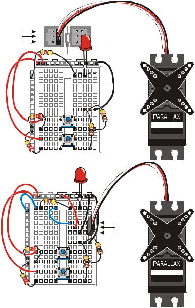
Figure 4-22 |
Red |
HomeWork Board |
Black |
Servo Circuit with |
|
Pushbutton Circuits |
|
Added |
|
standard servo |
|
www.parallax.com |

Chapter #4: Controlling Motion · Page 131
15 14 |
|
13 12 |
White |
|
|
Red |
|
Red |
Black |
|
Black |
X4 |
|
X5 |
Vdd |
Vin |
Vss |
X3 |
|
+ |
P15 |
|
|
|
|
|
P14 |
|
|
P13 |
|
|
P12 |
|
|
P11 |
|
|
P10 |
|
|
P9 |
|
|
P8 |
|
|
P7 |
|
|
P6 |
|
|
P5 |
|
standard servo |
P4 |
|
|
|
www.parallax.com |
|
P3 |
|
|
P2 |
|
|
P1 |
|
|
P0 |
|
|
X2 |
|
|
Figure 4-23
Board of Education Rev B Servo Circuit with Pushbutton Circuits Added
√Test the pushbutton connected to P3 using the original version of ReadPushbuttonState.bs2. The section that has this program and the instructions on how to use it begins on page 77.
√Modify the program so that it reads P4.
√Run the modified program to test the pushbutton connected to P4.
Programming Pushbutton Servo Control
Pushbutton servo control is not much different from pushbutton LED control. IF…THEN code blocks are used to check the pushbutton states and either add or subtract from a variable called duration. This variable is used in the PULSOUT command’s Duration argument. If one of the pushbuttons is pressed, the value of duration increases. If the other pushbutton is pressed, the value of duration decreases. A nested IF…THEN statement is used to decide if the duration variable is too large (greater than 1000) or too small (smaller than 500).