

Microcontroller based applied digital control (D. Ibrahim, 2006)
.pdfPIC MICROCONTROLLER INPUT–OUTPUT INTERFACE |
113 |
Solution
The program listing is shown in Figure 4.9. At the beginning of the program ports A and B are configured as outputs. Then the LCD is initialized and the string ‘CONTROL’ is sent to the LCD using the command lcd puts.
A more complex microcontroller example using an analog temperature sensor, an A/D converter and an LCD is given below.
Example 4.9
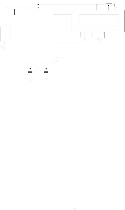
An LM35DZ type analog temperature integrated circuit is connected to analog input AN0 (or RA0) of a PIC16F877 microcontroller. Also, an LCD is connected to the microcontroller as shown in Figure 4.10. Write a program to display the ambient temperature every second on the LCD. The display should show the temperature as ‘TEMP = nn’, where nn is the ambient temperature. This is an example of a digital thermometer.
//*******************************************************************
//
//LCD DISPLAY PROGRAM
//====================
//Author: D. Ibrahim
//Date: May, 2005
// |
File: |
LCD.C |
// |
|
|
//This program sends the message CONTROL to an LCD.
//The LCD is connected to a PIC microcontroller as specified by the
//PIC C language compiler. The microcontroller is operated with a
//4MHz crystal.
//
//******************************************************************* #include <pic.h>
#include <delay.c> #include <lcd.c>
//
// Main Program |
|
// ************ |
|
// |
|
main(void) |
|
{ |
|
TRISA = 0; |
/* PORT A is output */ |
TRISB = 0; |
/* PORT B is output */ |
lcd init(); |
/* Initialize the LCD */ |
lcd clear(); |
/* Clear the display */ |
lcd puts("CONTROL"); |
/* Send text CONTROL to the LCD */ |
} |
|
Figure 4.9 Program listing for Example 4.8
114 PROGRAMMING PIC MICROCONTROLLERS IN C
+
Analog
Figure 4.10 Hardware set-up of the digital thermometer
Solution
The LM35DZ is a 3-pin integrated circuit which gives an output voltage which is directly proportional to the temperature. The device can be used to measure temperatures in the range 0–125◦ C. Two pins of the integrated circuit are connected to the supply and the ground. The third pin is the output Vo, where Vo = 10 mV/◦ C. Thus, for example, at 20 ◦C the output voltage is 200 mV, at 30◦C the output is 300 mV and so on. The sensor is directly connected to analog channel AN0 of the microcontroller. The LCD is connected as described in Example 4.8.
The program listing of the digital thermometer is given in Figure 4.11. At the beginning of the program bit 0 of port A is configured as input and port B is configured as output. Then, ADCON1 register is configured (see Chapter 3) by sending the bit pattern ‘10001110 = 0 × 8E’, so that the RA0 port pin is analog, and the RA2 and RA3 port pins are digital. Also, bit 7 (ADFM) of ADCON1 is set to 1 so that the 8 bits of the converted data will be in the register ADRESL and the upper 2 bits will be in bits 0 and 1 of the register ADRESH. The A/D converter clock is chosen as fosc/8 and channel 0 of the A/D converter is selected by configuring the ADCON0 register.
The A/D converter is started by setting bit 2 of the ADCON0 register (sending 0 × 45 to ADCON0). The program then waits (using a while loop) for the completion of the conversion. At the end of the conversion bit 2 of ADCON0 is cleared by the microcontroller and this is sensed by the program. The program then exits the while loop and reads the lower and upper bytes of the converted 10-bit data, combines the data into a single variable called temp, and then converts the data into real value, i.e. millivolts. The actual temperature in degrees Celsius is then obtained by dividing this voltage by 10. The temperature is then converted into a string called tempc and is sent to the LCD display using the lcd puts command. The program clears

//*******************************************************************
//
//DIGITAL THERMOMETER PROGRAM
//============================
//Author: D. Ibrahim
//Date: May, 2005
//File: THERMOMETER.C
//This program reads the temperature form a LM35DZ type analog
//sensor every second and then displays the temperature on an LCD.
//The microcontroller is operated with a 4MHz crystal.
//
//******************************************************************* #include <pic.h>
#include <delay.c> #include <lcd.c> #include <stdio.h>
//
// Function to wait a second
//
void wait a second()
{
unsigned int j;
for(j = 0; j < 4; j++)DelayMs(250);
}
// |
|
// Main Program |
|
// ************ |
|
// |
|
main(void) |
|
{ |
|
const float lsb = 5000.0/1024.0; |
|
float mV, temp, templ, temph; |
|
unsigned int tempc; |
|
unsigned char disp[] = "TEMP = |
"; |
TRISA = 1; /* RA0 is input, others output */
TRISB = 0; /* PORT B is output */
ADCON1 = 0x8E; /* RA0=analog, RA2,RA3=digital */
ADCON0 = 0x41; /* Configure A/D clock and select channel 0 */
for(;;)
{
ADCON0 = 0x45; /* Start A/D conversion */ while(ADCON0 & 4) != 0); /* Wait for conversion */ temph = ADRESH; /* Read upper 2 bits */
templ = ADRESL; /* Read lower 8 bits */
temp = 256.0*temph + templ; /* Temperature in digital */ mV = temp *lsb; /* Temperature in mV */
tempc = mV / 10.0; /* Temperature in Centig. (10mV/C) */ sprintf(disp+7, "%d",tempc); /* Convert temperature to a string */ lcd puts(tempc); /* Display temperature on LCD */
wait a second(); /* Wait a second */ lcd clear(); /* Clear display */
}
}
Figure 4.11 Program listing for Example 4.9

116 PROGRAMMING PIC MICROCONTROLLERS IN C
the LCD display and repeats continuously after 1 s delay. The delay is created by using a function called wait a second. The program displays the temperature as T E M P = nn where nn is the ambient temperature.
Notice that the program uses the header files <pic.h>, <delay.c>, <lcd.c>, and <stdio.h>. The file <pic.h> contains the PIC microcontroller definitions. <delay.c> is used to create delays in the program. <lcd.c> is used for the LCD initialization and control functions. Finally, <stdio.h> is used to convert an integer into a string so that it can be displayed on the LCD.
4.24 EXERCISES
1.Describe the differences between an unsigned char and a signed char.
2.Describe the differences between an int and a float.
3.Show how integer number 230 can be written in binary, octal and in hexadecimal.
4.Write a function which converts the temperature from ◦F to ◦C.
5.What will be the value of the variable z in the following program?
int f(x)
{
int p;
p = x++; return(p);
}
main(void)
{
int x, z; x = 10;
z = f(x);
}
6. The mathematical operation min(x, y) can be represented by the conditional expression
(x < y)?x:y
In a similar fashion, describe the mathematical operation min(x, y, z). 7. Write a function that reverses the bit pattern of a byte. For example,
00000001 reversing gives 1111110
8.Write a function which takes a variable x and shifts it n positions to the left.
9.Write the octal, hexadecimal and binary equivalents of the decimal integers 4, 6, 120, 254.
10.Write a function to multiply two polynomials of degree n.
11.Write a program which calls a function to calculate the sum of the squares of the elements of a matrix which has 10 elements.
FURTHER READING |
117 |
12.Explain how delays can be generated in PICC Lite programs. Describe how a 10 s delay can be generated using do loops.
13.Explain how data can be written to the EEPROM memory of a PIC microcontroller. Write a program to clear all the first 64 locations of the EEPROM memory.
14.Explain how data can be read from the EEPROM memory of a PIC microcontroller. Write a program to calculate the sum of all numbers stored in the first 20 locations of an EEPROM memory.
15.Eight LEDs are connected to port B of a PIC16F84 microcontroller. Write a program to turn on the odd-numbered LEDs, i.e. LEDs connected to port pins 1, 3, 5 and 7.
16.Eight LEDs are connected to port B of a PIC16F84 microcontroller. Also, a push-button switch is connected to port RA0. Write a program to turn on the LEDs clockwise when the switch is pressed, and anti-clockwise when the switch is released.
17.An LCD is connected to a PIC16F84 microcontroller. Write a program to display the string ‘My Computer’ on the LCD.
18.A PIC16F84 microcontroller is to be used as an event counter. An LCD is connected to the microcontroller in the standard way, and a switch is connected to bit 0 of port A. The switch is designed to close every time an external event occurs. Write a program which will count the events and display the total on the LCD continuously.
19.A PIC16F877 microcontroller is to be used to monitor the temperature of an oven and give an alarm if the temperature exceeds a pre-specified value. An LM35DZ type analog temperature sensor is to be used to measure the temperature of the oven every second. An
LED is connected to bit 0 of port b. (a) Draw the circuit diagram of the system. (b) Write a program that will turn on the LED if the oven temperature exceeds 50◦C.
FURTHER READING
[Anon, 2005a] |
Microchip Data on CDROM. Microchip Technology Inc., www.microchip.com. |
[Anon, 2005b] |
PICC Lite User’s Guide. Hi-Tech Software, www.htsoft.com. |
[Gomaa, 1984] |
Gomaa, H. A software design method for real-time systems. Commun. ACM, 27, 1984, |
|
pp. 938–949. |
[Gomaa, 1986] |
Gomaa, H. Software development for real-time systems, Commun. ACM, 29, 1986, |
|
pp. 657–668. |
[Ibrahim, 2002] |
Ibrahim, D. Microcontroller Based Temperature Monitoring and Control. Newnes, Lon- |
|
don, 2002. |
[Iovine, 2000] |
Iovine, J. PIC Microcontroller Project Book. McGraw-Hill, New York, 2000. |
[James, 1977] |
James, M.R. Microcontroller Cookbook PIC and 8051. Newnes, London, 1977. |
[Kalani, 1989] |
Kalani, G. Microprocessor Based Distributed Control Systems. Prentice Hall, Englewood |
|
Cliffs, NJ, 1989. |
[Kelley and Pohl, 1984] Kelley, A.L. and Pohl, I. A Book on C. The Benjamin/Cummings Publishing Co. Inc., Menlo Park, CA, 1984.

5
Microcontroller Project Development
5.1 HARDWARE AND SOFTWARE REQUIREMENTS
The development of a microcontroller based project requires hardware and software products. Hardware requirements generally depend on how complex the project is, but the following hardware products are normally required in almost all types of projects:
microcontroller programmer;
microcontroller development board or breadboard with the required components;
microcontroller chips;
PC;
test equipment such as a voltmeter, logic pulser or oscilloscope.
Figure 5.1 shows the basic hardware requirements. A microcontroller programmer is connected to a PC and is used to download the user program to the target microcontroller program memory. For flash type program memories no additional hardware is normally required. The development of systems based on EPROM type program memories requires an EPROM eraser device so that the microcontroller program memory can be erased and reprogrammed.
Small projects incorporating simple LEDs and buzzers can be developed using microcontroller development boards. These boards usually have built-in LEDs, switches, buzzers, etc. so that the user can test programs with simple to moderate complexity. Some development boards also incorporate chip programmer hardware so that the target microcontroller can be programmed on the same board. Complex projects can initially be built and tested on a breadboard. If the project is to be used in commercial or in industrial applications, then a printed circuit board design of the project is created.
A PC is required mainly for two purposes during the development of a microcontroller based project: the user program is developed and compiled on the PC, and the PC is used to transfer the user object code to the device programmer so that the program memory of the target microcontroller can be loaded with the user program.
Depending upon the complexity of the project, several types of test equipment may be required. For simple projects a voltmeter may be sufficient to test the static voltage levels around the circuit. For more complex projects, a logic analyser, logic pulser, frequency counter, or an oscilloscope may be required.
Microcontroller Based Applied Digital Control D. Ibrahim
C 2006 John Wiley & Sons, Ltd. ISBN: 0-470-86335-8
120 MICROCONTROLLER PROJECT DEVELOPMENT
|
|
|
|
|
|
|
|
|
|
|
|
|
|
|
|
|
|
|
|
|
|
|
|
|
|
|
|
|
|
|
|
|
|
|
|
|
|
|
|
|
|
|
|
|
|
|
|
|
|
|
|
|
|
|
|
|
|
|
|
|
|
|
|
|
|
|
|
|
|
|
|
|
|
|
|
|
|
|
|
|
|
|
|
|
|
|
|
|
Development board |
|
|
|
|
|
|
|
|
|
|
|
|
|
|
|
|
|
|
|
|
|
|
|
|
|
|
|
|
|
|
|
PC |
|
|
Programmer |
or Breadboard |
|||||||||
|
|
|
|
|||||||||||
|
|
|
|
|
|
|
|
|
|
|
|
|
|
|
|
|
|
|
|
|
|
|
|
|
|
|
|
|
|
|
|
|
|
|
|
|
|
|
|
|
|
|
|
|
|
|
|
|
|
|
|
|
|
|
|
|
|
|
|
Microcontroller chips
Figure 5.1 Microcontroller project development hardware
In addition to the above hardware, a number of software products will be required during the development of a microcontroller based product. The minimum required software is:
program development software;
microcontroller assembler (or compiler if a high-level language is used);
microcontroller device programmer software.
Program development software, or an editor, is required to write the program code. Most assemblers or compilers provide built-in editors and the user programs can be developed using these editors.
Once a program is written it has to be assembled or compiled if a high-level language is used. The object code is normally produced from the assembler or the compiler if the program contains no errors.
A microcontroller device programmer software is then required to transfer the object code to the program memory of the target microcontroller.
Depending on the complexity of the project, additional software products, such as simulators, debuggers or in-circuit emulators, can be used to test and verify the operation of a program.
Simulator programs are run on a PC and can be used without any project hardware. Simulators are extremely useful in single-stepping and testing the user programs before the program is loaded into the target hardware. Debuggers are similar to simulators, and some debuggers require the code to be loaded into the target microcontroller. The user can insert break-points using debuggers and then test the flow of data and control in a program.
In-circuit emulators can be used in complex projects. Using an emulator, the user can test a program very easily on the target hardware by inserting break-points, and by single-stepping using the target hardware. Although the in-circuit emulators can be very useful, they are usually very expensive.
5.2 PROGRAM DEVELOPMENT TOOLS
Historically, modular programming has been accepted as a good software design concept. Also known as structured programming, a software task is divided into smaller manageable tasks where each task is a self-contained piece of code, also called a module. Modules are
PROGRAM DEVELOPMENT TOOLS |
121 |
then designed using well-known constructs for sequence, selection and iteration. Although a structured approach to programming does not guarantee that a program will be free of errors, it helps to minimize the design errors and makes the final code much more readable and maintainable.
There are many tools available to help the programmer in the development and design of good programs. Some popular tools are: flow charts, structure charts, Unified Modeling LangaugeTM, Nassi–Schneidermann diagrams, Ferstl diagrams, Hamilton–Zeldin diagrams, and pseudocode. In this section we shall only look at some of the commonly used techniques. Further detailed information can be obtained from most books and papers on computer science.
5.2.1 Flow Charts
Flow charts have been around since the early days of programming. These type of charts are only useful for small applications. One of the disadvantages of flow charts is that the drawing and modifying the diagrams can be very timeconsuming. Flow charts also have the disadvantage that they tend to produce unstructured code which is very difficult to maintain. A typical flow chart is shown in Figure 5.2.
5.2.2 Structure Charts
Structure charts, also known as Jackson structured programming tools, were developed in the 1970s by Michael Jackson and became a widely used software design tool, especially in Europe.
Structure charts are similar to flow charts but are easier to draw and modify. Structure charts also tend to produce well-structured code which is easy to understand and maintain. The three basic operations of sequence, selection and iteration are shown differently using structure charts.
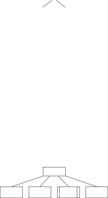
5.2.2.1 Sequence
Sequence is shown with rectangles drawn next to each other. The sequence of operations is from left to right. An example is given in Figure 5.3 where first the I/O port is initialized, then the LED is turned on, and finally the LED is turned off after a 5 s delay.
5.2.2.2 Selection
Selection is shown by placing a small circle at the top right-hand side of a rectangle. An example is given in Figure 5.4 where if condition1 is true then process B is performed, and if condition2 is true process C is performed.

122 MICROCONTROLLER PROJECT DEVELOPMENT
Figure 5.2 A typical flow chart
LED
CONTROL
Initialise |
|
Turn on LED |
|
Wait |
|
Turn off LED |
I/O Port |
|
|
5 seconds |
|
||
|
|
|
|
|
||
|
|
|
|
|
|
|
Figure 5.3 Example sequencing using structure charts
A
B° |
|
C° |
|
|
|
Figure 5.4 Example selection using structure charts
|
|
PROGRAM DEVELOPMENT TOOLS |
123 |
|||
|
|
|
|
|
|
|
|
|
A* |
|
|
|
|
|
|
|
|
|
|
|
B |
|
|
|
C |
|
|
|
|
|
|
|
|
|
Figure 5.5 Example iteration using structure charts
5.2.2.3 Iteration
Iteration is shown by placing an asterisk sign at the top right-hand side of a rectangle. An example is given in Figure 5.5 where processes B and C are repeated.
5.2.2.4 Invoking Modules
In structure charts modules can be shown with double-sided rectangles. An example is shown in Figure 5.6 where module ADD is called.
Example 5.1
Draw the structure chart for an application where three numbers are read from the keyboard into a main program, their sum calculated using a module called SUM, and the result displayed by the main program.
Solution
The structure chart for this example is shown in Figure 5.7.
5.2.3 Pseudocode
One of the disadvantages of graphical design methods such as flow diagrams and structure charts is that it can take a long time to draw them and that it is not easy to modify them.
Pseudocode is a kind of structured English for describing the operation of algorithms. It allows the programmer to concentrate on the development of the algorithm independent
ADD
Figure 5.6 Invoking a module