

PICmicro MCU C - An itroduction to programming The Microchip PIC in CCS C (N.Gardner, 2002)
.pdfBugs Errors created free of charge by you. These range from simpel typin errus to incorrect use of the software language syntax errors. Most of these bugs will be found by the compiler and shown up in a .LST file, others will have to be sought and corrected by trial and error.
Microprocessor
A microprocessor or digital computer is made up of three basic sections: CPU, I/O and Memory – with the addition of some support circuitry.
Each section can vary in complexity from the basic to all bells and whistles.
|
|
|
DATA |
|||
I/O |
|
|
|
|
|
MEMORY |
DIGITAL |
|
|
|
|
|
|
PWM |
|
|
|
|
|
RAM |
ANALOG |
|
|
|
|
|
EPROM |
RS232 |
|
|
|
|
|
EEPROM |
|
|
|
||||
I2C |
|
|
|
|
|
|
|
ADDRESS |
|
|
ADDRESS |
||
|
|
|
CPU |
|
|
|
|
|
|
4, 8, 16 BIT |
|
|
|
|
|
|
||||
|
|
|
|
|
|
|
|
|
|
|
|
|
|
|
|
|
|
|
|
|
|
|
|
|
|
|
|
WATCHDOG |
OSCILLATOR |
|
TIMER |
||
|
TYPICAL MICROPROCESSOR SYSTEM
Taking each one in turn:
Input/output (I/O) can comprise digital, analog and special functions and is the section which communicates with the outside world.
The central processor unit (CPU) is the heart of the system and can work in 4, 8, or 16 bit data formats to perform the calculations and data manipulation.
The memory can be RAM, ROM, EPROM, EEPROM or any combination of these and is used to store the program and data.
An oscillator is required to drive the microprocessor. Its function is to clock data and instructions into the CPU, compute the results and then output the information. The oscillator can be made from discrete components or be a ready made module.
11
Other circuitry found associated with the microprocessor are the watch dog timer – to help prevent system latch up, buffering for address and data busses to allow a number of chips to be connected together without deteriorating the logic levels and decode logic for address and I/O to select one of a number of circuits connected on the same bus.
It is normal to refer to a Microprocessor as a product which is mainly the CPU area of the system. The I/O and memory would be formed from separate chips and require a Data Bus, Address Bus and Address Decoding to enable correct operation.
Microcontrollers
The PICmicro®MCU, on the other hand, is a Microcontroller and has all the CPU, memory, oscillator, watchdog and I/O incorporated within the same chip. This saves space, design time and external peripheral timing and compatibility problems, but in some circumstances can limit the design to a set memory size and I/O capabilities.
The PIC family of microcontrollers offers a wide range of I/O, memory and special functions to meet most requirements of the development engineer.
You will find many general books on library shelves exploring the design of microcontrollers, microprocessors and computers, so the subject will not be expanded or duplicated here other than to explain the basic differences.
Why use the PIC
Code Efficiency The PIC is an 8 bit Microcontroller based on the Harvard architecture – which means there are separate internal busses for memory and data. The throughput rate is therefore increased due to simultaneous access to both data and program memory. Conventional microcontrollers tend to have one internal bus handling both data and program. This slows operation down by at least a factor of 2 when compared to the PICmicro®MCU.
Safety All the instructions fit into a 12 or 14 bit program memory word. There is no likelihood of the software jumping onto the DATA section of a program and trying to execute DATA as instructions. This can occur in a non Harvard architecture microcontroller using 8-bit busses.
Instruction Set There are 33 instructions you have to learn in order to write software for the 16C5x family and 14 bits wide for the 16Cxx family.
Each instruction, with the exception of CALL, GOTO or bit testing instructions (BTFSS, INCFSZ), executes in one cycle.
Speed The PIC has an internal divide by 4 connected between the oscillator
12
and the internal clock bus. This makes instruction time easy to calculate, especially if you use a 4 MHz crystal. Each instruction cycle then works out at 1 uS. The PIC is a very fast micro to work with e.g. a 20MHz crystal steps through a program at 5 million instructions per second! – almost twice the speed of a 386SX 33!
Static Operation The PIC is a fully static microprocessor; in other words, if you stop the clock, all the register contends are maintained. In practice you would not actually do this, you would place the PIC into a Sleep mode – this stops the clock and sets up various flags within the PIC to allow you to know what state it was in before the Sleep. In Sleep, the PIC takes only its standby current which can be less the 1uA.
Drive Capability The PIC has a high output drive capability and can directly drive LEDs and triacs etc. Any I/O pin can sink 25mA or 100mA for the whole device.
Options A range of speed, temperature, package, I/O lines, timer functions, serial comms, A/D and memory sizes is available from the PIC family to suit virtually all your requirements.
Versatility The PIC is a versatile micro and in volume is a low cost solution to replace even a few logic gates; especially where space is at a premium.
13
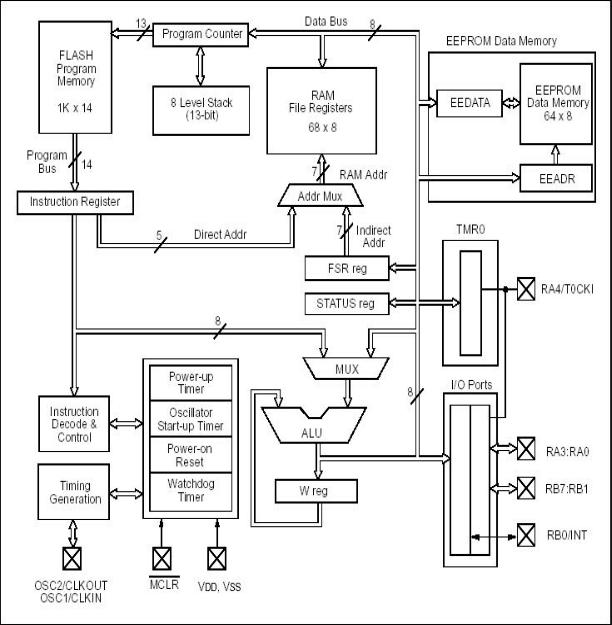
PIC FUNCTION BLOCK DIAGRAM
PIC16F84A(14Bit) BLOCK DIAGRAM
14
Security The PICmicro®MCU has a code protection facility which is one of the best in the industry. Once the protection bit has been programmed, the contents of the program memory cannot be read out in a way that the program code can be reconstructed.
Development The PIC is available in windowed form for development and OTP (one time programmable) for production. The tools for development are readily available and are very affordable even for the home enthusiast.
Trying and Testing Code
Getting to grips with C can be a daunting task and the initial outlay for a C compiler, In Circuit Emulator and necessary hardware for the PIC can be prohibitive at the evaluation stage of a project. The C compiler supplied on this disk was obtained from the Internet and is included as a test bed for code learning. Basic code examples and functions can be tried, tested and viewed before delving into PIC specific C compilers which handle I/O etc.
C Coding Standards
Program writing is like building a house – if the foundations are firm, the rest of the code will stack up. If the foundations are weak, the code will fall over at some point or other. The following recommendations were taken from a C++ Standards document and have been adapted for the PIC.
Names – make them fit their function
Names are the heart of programming so make a name appropriate to its function and what it’s used for in the program.
Use mixed case names to improve the readability
ErrorCheck is easier than ERRORCHECK
Prefix names with a lowercase letter of their type, again to improve readability:
g |
Global |
gLog; |
r |
Reference |
rStatus(); |
s |
Static |
sValueIn; |
Braces{}
Braces or curly brackets can be used in the traditional UNIX way
if (condition) {
…………….
}
or the preferred method which is easier to read
if (condition)
15
{
…………….
}
Tabs and Indentation
Use spaces in place of tabs as the normal tab setting of 8 soon uses up the page width. Indent text only as needed to make the software readable. Also, tabs set in one editor may not be the same settings in another – make the code portable.
Line Length
Keep line lengths to 78 characters for compatibility between monitors and printers.
Else If Formatting
Include an extra Else statement to catch any conditions not covered by the preceding if’s
if (condition)
{
}
else if (condition)
{
}
else
{
……….. /* catches anything else not covered above */
}
Condition Format
Where the compiler allows it, always put the constant on the left hand side of an equality / inequality comparison, If one = is omitted, the compiler will find the error for you. The value is also placed in a prominent place.
if ( 6 == ErrorNum) …
Initialize All Variables
Set all variables to a known values to prevent ‘floating or random conditions’ int a=6, b=0;
Comments
Comments create the other half of the story you are writing. You know how your program operates today but in two weeks or two years will you remember, or could someone else follow your program as it stands today? Use comments to mark areas where further work needs to be done, errors to be debugged or future enhancements to the product.
16
Basics
All computer programs have a start. The start point in Microcontrollers is the reset vector. The 14 bit core (PIC16Cxx family) reset at 00h, the 12 bit core (PIC16C5x and 12C50x) reset at the highest point in memory – 1FFh, 3FFh, 7FFh.
The finish point would be where the program stops if run only once e.g. a routine to set up a baud rate for communications. Other programs will loop back towards the start point such as traffic light control. One of the most widely used first programming examples in high level languages like Basic or C is printing ‘Hello World’ on the computer screen.
Using C and a PC is straightforward as the screen, keyboard and processor are all interconnected. The basic hooks need to be placed in the program to link the program to the peripherals. When developing a program for the PICmicro®
MCU or any microprocessor / microcontroller system, you need not only the software hooks but also the physical hardware to connect the micro to the outside world. Such a system is shown below.
17
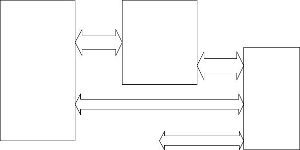
DATA |
ICE |
PC |
DATA |
|
TARGET BOARD
COMMS
I/O
Using such a layout enables basic I/O and comms to be evaluated, tested and debugged. The use of the ICE, through not essential, speeds up the development costs and engineer’s headaches. The initial investment may appear excessive when facing the start of a project, but time saved in developing and debugging is soon outstripped.
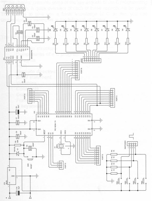
The hardware needed to evaluated a design can be a custom made PCB, protoboard or an off the shelf development board such as our PICmicro®MCU Millennium board contains (someone had to do one!). The Millennium board contains all the basic hardware to enable commencement of most designs while keeping the initial outlay to a minimum.
Assemble the following hardware in whichever format you prefer. You WILL need a PIC programmer such as the PICSTART Plus as a minimal outlay in addition to the C compiler.
A simple program I use when teaching engineers about the PIC is the ‘Press button – turn on LED’. Start with a simple code example – not 2000 lines of code!
In Assembler this would be:-
main |
btfss |
porta,switch |
;test for switch closure |
|
got |
main |
;loop until pressed |
|
bsf |
portb,led |
;turn on led |
lp1 |
btfsc |
porta,switch |
;test for switch open |
|
goto |
lp1 |
;loop until released |
|
bcf |
portb,led |
;turn off led |
|
goto |
main |
;loop back to start |
In C this converts to
18
main() |
|
|
|
{ |
|
|
|
set_tris_b(0x00); |
//set port b as outputs |
||
while(true) |
|
|
|
{ |
|
|
|
if (input(PIN_A0)) |
//test for switch closure |
||
output_high(PIN_B0); |
//if closed turn on led |
||
else |
|
|
|
output_low(PIN_B0); |
//if open turn off led |
||
} |
|
|
|
} |
|
|
|
When assembled, the code looks like this:- |
|
|
|
main() |
|
|
|
{ |
|
|
|
set_tris_b(0x00); |
0007 |
MOVLW |
00 |
|
0008 |
TRIS |
6 |
while(true) |
|
|
|
{ |
|
|
|
if (input(PIN_A0)) |
0009 |
BTFSS |
05,0 |
|
000A |
GOTO |
00D |
output_high(PIN_B0); |
|
|
|
|
000B |
BSF |
06,0 |
else |
|
|
|
|
000C |
GOTO |
00E |
output_low(PIN_B0); |
|
|
|
|
000D |
BCF |
06,0 |
} |
|
|
|
|
000E |
GOTO |
009 |
}
As you can see, the compiled version takes more words in memory – 14 in C as opposed to 9 in Assembler. This is not a fair example on code but as programs get larger, the more efficient C becomes in code usage.
19
20