

PICmicro MCU C - An itroduction to programming The Microchip PIC in CCS C (N.Gardner, 2002)
.pdfRS |
- |
Record Separator |
SI |
- |
Shift In |
US |
- |
Unit Separator |
DEL |
- |
Delete |
SP |
- |
Space (blank) |
|
|
|
DC1 |
- |
Xon |
DC3 |
- |
Xoff |
RS232 Handshaking
COMPUTER POWERED UP
AND OK
DTR = 1
MODEM POWERED UP AND
OK
DSR = 1
COMPUTER
MODEM OK TO SEND
CTS = 1
COMPUTER
TX DATA
MODEM
Typical Null Modem Connections
Simple RS232 Tester
121

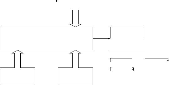
USART |
|
|
BAUD RATE GENERATOR |
TRANSMIT STATUS |
|
SPBRG |
TXSTA |
|
|
TRANSMIT REGISTER |
|
|
TXREG |
|
TXIF |
RECEIVE REGISTER |
|
RCREG |
||
|
||
RCIF |
|
|
INTERRUPT STATUS |
RECEIVE STATUS |
|
PIR1 |
RCSTA |
C6 TX
TRISC
C7 RX
The USART operates in one of three modes: Synchronous Master, Synchronous Slave and Asynchronous, the latter being the most common for interfacing peripherals. Besides the obvious interface to PC’s and Modems, the USART can interface to A/D, D/A and EEPROM devices.
Data formats acceptable to the USART are: 8 or 9 data bits; none; odd or even parity; created and tested in user software; not a hardware function; and indication of over run or framing errors on the received data. In Asynchronous mode, the USART can handle full duplex communications, but only half duplex in Synchronous mode. There are pre-set functions which speed up application writing:
#use |
fixed_io(c_outputs=pin_C6) |
//speeds up port use |
#use |
delay(Clock=4000000) |
//clock frequency |
#use rs232(baud=4800, xmit=PIN_C6, rcv=PIN_C7)
122
The CCS compiler has the ability to use the on-board PICmicro®MCU’s UART if one is present. If the UART is available in hardware, the code generated will use the existing hardware. If, however, the hardware is absent, the resulting code generated will be larger. With the exception of the interrupt on transmit and receive, the code behaves like hardware UART. The software UART has the ability to invert the output data levels, removing the need for an external driver/level shifter in logic level applications. This function is not available in hardware.
This code transparency enables code to be moved from one PICmicro®MCU application to another with minimal effect.
Included in the C compiler are ready-made functions for communications such as:
getc, getch, getchar |
waits for and returns a character to be received |
|
from the RS232 rev pin |
gets(char *string) |
reads s string of characters into the variable until |
|
a carriage return is received. A 0 terminates the |
|
string. The maximum length of characters is |
|
determined by the declared array size for the |
|
variable. |
putc put char |
sends a single character to the RS232 xmit pin |
puts(s) |
sends a string followed by a line feed and |
|
carriage return |
The function kbhit() may be used to determine if a character is ready. This may prevent hanging in getc() waiting for a character. The following is an example of a function that waits up to one-half second for a character.
char timed_getc()
{
long timeout; timeout_error=FALSE; timeout=0;
while(!kbhit&&(++timeout<50000)) //1/2 second delay_us(10);
if(kbhit)
return(getc()); else
{
timeout_error=TRUE; return(0);
}
}
9.7I2C Communication
123
I2C is a popular two-wire communication bus to hardware devices. A single two wire I2C bus has one master and any number of slaves. The master may send or request data to/from any slave. Each slave has a unique address.
The two wires are labeled SCL and SDA. Both require a pull-up resistor (1-10K) to +5V.
Communication begins with a special start condition, followed by the slave address. The LSB of this first byte indicates the direction of data transfer from this point on. Data is transferred and the receiver specifically acknowledges each byte. The receiver can slow down the transfer by holding SCL low while it is busy. After all data is transferred, a stop condition is sent on the bus.
The following is an example C program that will send three bytes to the slave at address 10 and then read one byte back.
#include <16C74.h>
#fuses XT, NOWDT
#use delay(clock=4000000)
#use I2C(master, SCL=PIN_B0, SDA=PIN_B1) main()
{
int data; I2C_START();
I2C_WRTIE(10);
I2C_WRTIE(1);
I2C_WRTIE(2);
I2C_WRTIE(3); I2C_STOP(); I2C_START();
I2C_WRTIE(11); data=I2C_READ();
I2C_STOP();
}
9.8SPI Communication
Like I2C, SPI is a two or three wire communication standard to hardware devices. SPI is usually not a bus, since there is one master and one slave.
One wire supplies a clock while the other sends or receives data. If a third wire is used, it may be an enable or a reset. There is no standard beyond this, as each device is different.
The following is C code to send a 10 bits command MSB first to a device.
Note: The shift_left function returns a single bit (the bit that gets shifted out) and this bit is the data value used in the output_bit function.
124
main() |
|
{ |
|
long cmd; |
|
cmd=0x3e1; |
|
for(i=1;i<=6;i++) |
//left justify cmd |
shift_left(cmd,3,0); |
|
output_high(PIN_B0); |
//enable device |
//send out 10 data bits each with a clock
pulse
for(i=0;i<=10;++i)
{
output_bit(PIN_B1, shift_left(cmd,2,0)); output_high(PIN_B2); //B2 is the clock output_low(PIN_B2);
}
output_low(PIN_B1); |
//disable device |
output_low(PIN_B0); |
|
}
The following is C code to read a 8 bits response. Again shift_left is used, and the data that is shifted in is bit on the input pin.
main()
{
int data;
output_high(PIN_B0); //enable device //send a clock pulse and
//read a data bit eight times
for(i=0;i<=8;++i)
{
output_high(PIN_B2); output_low(PIN_B2); shift_left(&data,1,input(PIN_B1));
}
output_low(PIN_B0); |
//disable device |
}
The previous are two great examples of shifting data in and out of the PICmicro®MCU a bit at a time. They can be easily modified to talk to a number of devices. Slower parts may need some delays to be added.
Some PIC’s have built in hardware for SPI. The following is an example of using the built in hardware to write and read.
main()
{
int data;
setup_spi(SPI_MASTER | SPI_H_TO_L | SPI_CLK_DIV_16); output_high(PIN_B0);
125
spi_write(3); spi_write(0xE1); output_low(PIN_B0); output_high(PIN_B0); data=spi_read(0); output_low(PIN_B0);
}
Note: Built in hardware does have restrictions. For example, the above code sent 16 bits not 10. Most SPI devices ignore all bits until the first 1 bit, so this will still work.
9.9PWM Generation
TMR2 |
|
PR2 |
|
(PERIOD COURSE) |
|
|
(PERIOD DINE) |
|
|
|
|
PWM1 C2
COMPARATOR
PWM2 C1
PERIOD
DUTY CYCLE
CCPR1L |
CCPR2L |
|
||
PWM1 |
PWM2 |
|
|
|
(DUTY CYCLE) |
(DUTY CYCLE) |
|
|
|
|
|
|
|
|
For PICmicro®MCU’s with PWM generation hardware, once the registers are set up, the PWM runs on its own without constant software involvement. Calculation of the PWM values is best achieved with a simple spreadsheet. Example:
PWM setup – frequency = 600Hz M/S ratio = 1:1
Prescale value = ((1/PWM Frequency)/Prescale value * (4/OSC frequency))-1 PWM resolution = ( log ( OSC freq / PWM freq ) ) / log 2
So for the above example, a 600Hz PWM with a 4MHz oscillator and /16 prescaler will give 103.2 to load into the PR2 register and a resolution of 12.7 bits
setup_timer_2(mode, period, postscale) initializes timer 2 where mode is
T2_DISABLED
T2_DIV_BY_1
T2_DIV_BY_4
126
T2_DIV_BY_16
period is an offset value between 0 and 255 before the timer resets postscale is a value between 0 and 16 to determine the times before an interrupt occurs
set_pwm1_duty(value)
this will write the 10 bit value to the PWM module set_pwm2_duty(value)
If only 8 bits are sent, the 2 lsb’s will be ignored. Note, value is in the range 0 to period
set_ccp1(CCP_PWM), set_ccp2(CCP_PWM)
this function will initialize the CCP in a PWM mode
Example:
setup_ccp1(CCP_PWM); //sets up for pwm setup_timer_2(T2_DIV_BY_4, 140, 0);
//140 as offset, timer 4
set_pwm1_duty(70);
//50% duty cycle, i.e. half of 140
If oscillator = 4MHz, then frequency will be 1.773KHz with a potential resolution of 11 bits
The following example will generate one of two tones – determined by the value passed to the routine – for a set duration. The frequency is set with the:
setup_timer_2(T2_DIV_BY_4, 100, 0);
The duty ratio is set with
set_pwm1_duty(50);
The frequencies for the two tones are 2.475KHz and 996Hz. The duration is set with a simple delay followed by setting the duty cycle to – silence the output even though the PWM is still running.
void sound_bell(byte y) |
|
{ |
|
setup_ccp1(CCP_PWM); |
//configure CCP1 as a PWM |
if(y==2) |
|
{ |
|
setup_timer_2(T2_DIV_BY_4, 100, 0); set_pwm1_duty(50); //make this value half of tone delay_ms(200); //0.2 second bell from
terminal
}
else
127
{
setup_timer_2(T2_DIV_BY_4, 250, 0); set_pwm1_duty(125); //make this value half of tone delay_ms(300); //0.2 second bell from
terminal
}
set_pwm1_duty(0);
}
NOTE:
PICmicro®MCU’s without PWM hardware cannot have the function generated by software, unlike the USART function. However, PWM like functions can be simulated.
For example:
while(true)
{
output_high(PIN_B0); delay_us(500); output_low(PIN_B0); delay_us(500);
}
This will generate a 1KHz square wave. However, the PIC is dedicated to this operation and cannot do anything else. This can be overcome by toggling the pin in an interrupt routine, set to go off at a fixed rate.
9.10LCD Display Driving
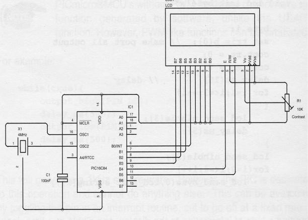
One of the most common display interfaces to PICmicro®MCU based designs is an LCD display based on the Hitachi controller. There are two modes of operation, 4 and 8 wires, with the option of write/delay or write/check busy when sending data to the display. It is an advantage to have a copy of the current display data sheet, when writing software, showing correct timing and setup codes.
A typical interface circuit is shown below. The PIC interfaces to the display in a 4 bits mode. Register Select (RS) changes between control and data register banks within the display, and the Enable (E) is used to strobe data into the display. In the 4 bits mode, the most significant nibble is sent first.
The initialization code looks like:
byte CONST LCD_INIT_STRING[5] =
{0x28, 0x06, 0x0c, 0x01, 0x80};
//send to the LCD to start it up //see data sheet
void lcd_init(byte x)
128
{
byte i;
set_tris_b(0); //make port all output cont.rs = 0;
cont.en = 0; delay_ms(15); for(i=1;i<=3;++i)
{
lcd_send_nibble(3); delay_ms(5);
}
lcd_send_nibble(2); for(i=0;i<=4;i++)
lcd_send_byte(0,lcd_init_string[i]);
}
Sending a byte of information to the display, one nibble at a time, looks like:
void lcd_send_byte(byte address, byte n)
{ |
|
cont.rs = address; |
|
delay_cycle(1); |
|
delay_cycle(1); |
|
cont.en = 0; |
|
lcd_send_nibble(n >> 4); |
//shift upper nibble 4 |
places |
|
lcd_send_nibble(n & 0xf); |
//mask off upper nibble |
delay_ms(10); |
|
} |
|
The function lcd_send_nibble does the strobe function:
void lcd_send_nibble(byte n) |
|
|
{ |
|
|
lcd_data = n; |
//place data |
on port |
delay_cycle(1); |
//delay 1 cycle |
|
cont.en = 1; |
//set enable |
high |
delay_us(2); |
//delay 2us |
|
cont.en = 0; |
//set enable |
low |
} |
|
|
129
Another function, which is useful when dealing with LCD displays, is the scroll. This is not the built in left/right scroll, but a software scroll up function. The following example is used to place the latest text on the bottom line of a 4 line display, and scroll the previous line and the other 3 up by one. The top line then scrolls off the display and is lost.
byte Line1[0x10]; |
//setup arrays to hold data |
byte Line2[0x10]; |
|
byte Line3[0x10]; |
|
byte Line4[0x10]; |
|
memcpy(Line1, Line2, 0x10); |
//transfer data from |
one |
|
memcpy(Line2, Line3, 0x10); |
//array to the next |
memcpy(Line3, Line4, 0x10); |
//and again |
memset(Line4, 0x20, 0x10); |
//and clear bottom line |
lcd_same_line(0); |
//go to start of |
display |
|
for(i=0;i<==0x0f;++i) |
|
{ |
|
k = Line1[i]; |
//send data from line1 |
lcd_send_byte(1,k); |
//memory array to display |
}//repeat for other 3 lines
9.11Interrupts
130