

Chapter 1 |
Pinch Technology |
41 |
•Exploit heat load loops and heat load paths
•Optimise network performance using advanced tools in SuperTarget PROCESS
1.10.5Heat Exchanger Network Design for Retrofits
PinchExpress and SuperTarget PROCESS provide the necessary tools for retrofit design using one of the three methods.
1.Pinch Design Method with maximum re-use of existing exchangers
2.Correction of Cross-Pinch Exchangers
3.Analysis of Exchanger Paths
Which Retrofit Method is Suitable?
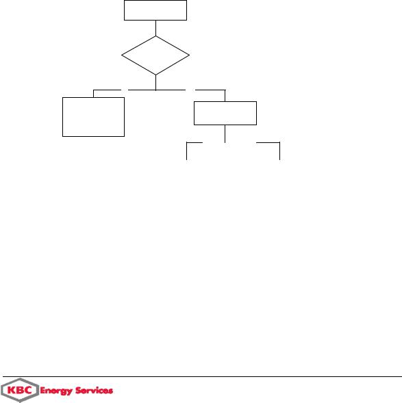
The first step in retrofit design is to decide which retrofit method is most suitable for the project. The hierarchical diagram shown in the figure below indicates when each of the three methods is suitable. Detailed explanation of the methods is provided in the following sections. The screen shots used in these sections are taken from PinchExpress, but are equally applicable to SuperTarget PROCESS.
Retrofit project with large scope for savings
Is the current heat integration significant?
No
Pinch Design Method
Re-use existing exchangers
Yes
Are composite curves parallel with little use of intermediate utilities?
No |
|
Yes |
|
Cross-Pinch |
|
Path Analysis |
Analysis |
|
|
|
|
|
|
|
|
Hierarchy of retrofit design
Pinch Design Method with maximum re-use of existing exchangers
This method has been described in the previous section for design from grassroots. The method is briefly described for retrofits as:
a)Delete the existing network as shown in the figure below
b)Re-design the network by following the Pinch Design Method
Pinch Technology Introduction

42 |
Pinch Technology |
Chapter 1 |
c) Re-use existing exchangers in place of new ones between the same streams
Delete existing network before applying the pinch Design Method
Correcting Cross-Pinch Exchangers
In situations where the existing network already involves many process-process heat exchangers, it is not appropriate to delete the entire network in order to apply the Pinch Design Method. Instead, it is better to apply a method that makes incremental changes to the existing network, with a corresponding quantification of the benefits.
This is particularly true of processes with diverging composite curves and significant use of intermediate utilities. Indeed, for such a process it is usually possible to discover a series of independent retrofit projects, each involving just a few modifications to the network. It is then possible to rank these projects and just choose the best ones according to some practical or economic criteria.
The method is described in the following flowchart:
Use cross-pinch analysis to find a promising project in the current network
Use the Grid Diagram to design the project
Yes
Record the savings achieved by this project
Are there any significant savings left?
No
Rank the projects according to the savings achieved, the number of modifications required etc.
Finished

Chapter 1 |
Pinch Technology |
43 |
Procedure for correcting cross-pinch exchangers
An Ammonia Synthesis example will be used to explain the steps involved in this method. The Balanced Composite Curves for this example show a scope for saving of 98.4% with a significant use of intermediate utilities.
Example for retrofit design using Cross-Pinch Analysis
Use cross-pinch analysis to find a promising project in the current network
1.From the 'Pinches' report of the potential savings window, identify the pinch region with the largest monetary savings potential and note the corresponding pinch temperature.
Pinches report indicate that the most significant pinch region is U:377.09 (HP-Steam (gen))
2.From the 'Penalties' report of the potential savings window, identify the exchanger with the largest cross-pinch duty in this region. Alternatively, use the Energy Penalties graph for the same purpose.
Pinch Technology Introduction

44 |
Pinch Technology |
Chapter 1 |
The largest penalty at U:377.09 is exchanger FDEF
3.Determine what will be required to correct the cross-pinch. The options are as follows:
a)Reduce the duty of the exchanger, or delete it altogether. This can be tested by simply editing the exchanger and seeing if there is a benefit (according to the Summary report of the potential savings window). Save the data file first, so that you can undo the change if necessary by reloading the file.
If this approach is used on a complete network then the reported savings can be achieved by simply replacing the duty with appropriate heaters and coolers. In other cases, there may be a need for additional heat exchange with the previously unmatched streams.
b)Move one end of the exchanger to a different utility. This can be done by simply dragging the end of the match with the mouse. Again, the Summary report will immediately show any benefit
c)Look for projects involving two or more exchangers. For example, remove the crosspinch by changing one of the inlet temperatures rather than reducing the duty. However, to do this you must compensate by a corresponding change to adjacent exchangers, heaters or coolers.
As with option (a), you can test the benefit of changing several matches by deleting them together and observing the reported savings. Again, save the data file first, so that you can undo the change by just reloading the file.
In the example, virtually all of the savings can be achieved by removing the cross-pinch in exchanger "FDEF". This is done by decreasing the hot inlet temperature to FDEF and reducing the duty of the cooler (Q_D6) by a corresponding amount. We can prove the benefit of this by temporarily deleting FDEF and Q_D6 and observing the increase in the "%SinceBase" column on the Summary report of the potential savings window.
The benefit reported after deleting exchanger FDEF and cooler Q_D6