


Chapter 1 |
Pinch Technology |
23 |
•Decrease in hot stream duty below the pinch.
•Increase in cold stream duty below the pinch
This is termed as the "+/- principle" for process modifications. This simple principle provides a definite reference for any adjustment in process heat duties, such as vaporisation of a recycle, pump-around condensing etc., and indicates which modifications would be beneficial and which would be detrimental.
Modifying the process, (a) The +/- principle for process modifications (b) Temperature changes can affect the energy targets only if streams are shifted through the pinch.
Often it is possible to change temperatures rather than heat duties. It is clear from Figure (a) that temperature changes that are confined to one side of the pinch will not have any effect on the energy targets. Figure (b) illustrates how temperature changes across the pinch can change the energy targets. Due to the reduction in feed vaporisation (FV) pressure, the feed vaporisation duty has moved from above to below the pinch. As a result the process energy target is reduced by the vaporisation duty. This can be considered as an application of +/- principle twice.
Thus the beneficial pattern for shifting process temperatures can be summarised as follows:
•Shift hot streams from below the pinch to above the pinch
•Shift cold streams from above the pinch to below the pinch
The +/- principle is in line with the general idea that it ought to be beneficial to increase the temperature of hot streams (this must make it easier to extract heat from them) and that likewise reduce the temperature of the cold streams. Changing the temperature of streams in this fashion will improve the driving forces in the heat exchanger network but can also decrease the energy targets if the temperature changes extend across the pinch. The designer can predict which modifications would be beneficial, detrimental, or inconsequential ahead of design.
1.8.2 Distillation Columns
Distillation columns are one of the major consumers of energy in chemical processes. In this section the principles for appropriate modification of distillation columns and their integration with the remaining process are considered. Firstly pinch analysis for stand-alone modification
Pinch Technology Introduction

24 |
Pinch Technology |
Chapter 1 |
of distillation columns is considered, followed by principles for appropriate integration of distillation columns with the remaining process.
The SuperTarget COLUMN module provides an advanced software tool for the implementation of standalone column modifications. PinchExpress and SuperTarget PROCESS provide tools for assessing the impact of column heat integration within a process.
Stand-alone column modifications
There are several options for improving energy efficiency of distillation columns. These include reduction in reflux ratio, feed conditioning and side condensing/reboiling etc. Using pinch analysis it is possible to identify which one of these modifications would be appropriate for the column and what would be the extent of the modification.
The Column grand composite curve
Figure 1: Procedure for obtaining Column Grand Composite Curve
The tool that is used for column thermal analysis is called the Column Grand Composite Curve (CGCC) [15], an example of which is shown in Figure 1 above. The procedure for obtaining the CGCC starts with a converged column simulation as shown in the figure. From the simulation, the necessary column information is extracted on a stage-wise basis. This information can then processed (for example by using the SuperTarget COLUMN module) to generate the CGCC as shown in Figure 1(b).
The CGCC, like the grand composite curve for a process, provides a thermal profile for a column and is used for identifying appropriate targets for the column modifications such as side condensing and reboiling as shown in the figure. In a normal column energy is supplied to the column at reboiling and condensing temperatures. The CGCC relates to minimum thermodynamic loss in the column or "Ideal Column" operation (see Figure 1(c)). For ideal column operation the column requires infinite number of stages and infinite number of side reboilers and condensers as shown in Figure 1(c). In this limiting condition, the energy can be supplied to the column along the temperature profile of the CGCC instead of supplying it at extreme reboiling and condensing temperatures. The CGCC is plotted in either T-H or Stage- H dimensions. The pinch point on the CGCC is usually caused by the feed.
Modifications using the Column grand composite curve
Chapter 1 |
Pinch Technology |
25 |
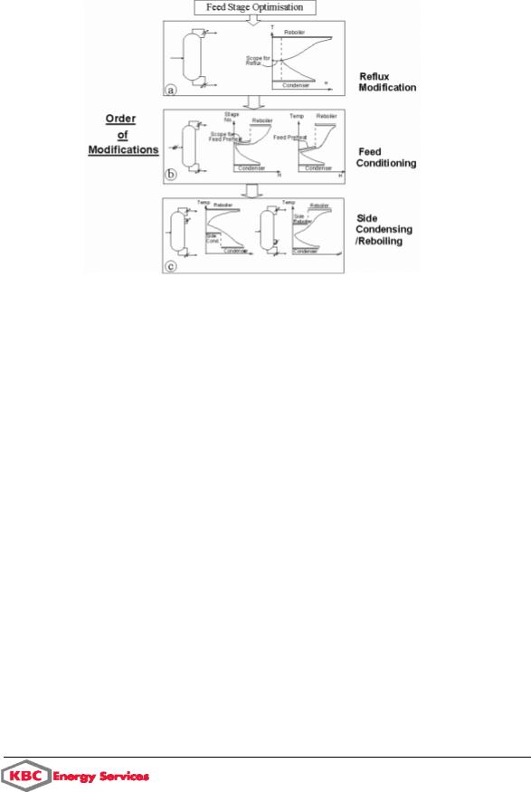
The figure below shows the use of the CGCC in identifying appropriate stand-alone column modifications. Firstly, the feed stage location of the column must be optimised in the simulation prior to the start of the column thermal analysis. This can be carried out by trying alternate feed stage locations in simulation and evaluating its impact on the reflux ratio. The feed stage optimisation is carried out first since it may strongly interact with the other options for column modifications. The CGCC for the column is then obtained.
Figure 2: Using Column Grand Composite Curve to identify column modifications
As shown in Figure 2(a) the horizontal gap between the vertical axis and CGCC pinch point indicates the scope for reflux improvement in the column. As the reflux ratio is reduced, the CGCC will move close to the vertical axis. The scope for reflux improvement must be considered first prior to other thermal modifications since it results in direct heat load savings both at the reboiler and the condenser level. In an existing column the reflux can be improved by addition of stages or by improving the efficiency of the existing stages.
After reflux improvement the next priority is to evaluate the scope for feed preheating or cooling (see Figure 2(b)). This is identified by a "sharp change" in the stage-H CGCC shape close to the feed as shown in the figure with a feed preheating example. The extent of the sharp change approximately indicates the scope for feed preheating. Successful feed preheating allows heat load to be shifted from reboiler temperature to the feed preheating temperature. Analogous procedure applies for feed pre-cooling.
After feed conditioning, side condensing/reboiling should be considered. Figure 2(c) describes CGCC's which show potential for side condensing and reboiling. An appropriate side reboiler allows heat load to be shifted from the reboiling temperature to a side reboiling temperature without significant reflux penalty.
In general, feed conditioning offers a more moderate temperature level than side condensing/reboiling. Also feed conditioning is external to the column and is therefore easier to implement than side condensing and reboiling. The sequence for the different column modifications can be summarised as follows:
1. Feed stage location
Pinch Technology Introduction

26 |
Pinch Technology |
Chapter 1 |
2.Reflux improvement
3.Feed preheating/cooling
4.Side condensing/reboiling.
Column integration
In the previous section, ways of improving column thermal efficiency by stand alone column modifications were considered. In many situations it is possible to further improve the overall energy efficiency of the process by appropriate integration of the column with the background process. By "column integration" a heat exchange link is implied between the column heating/cooling duties and the process heating/cooling duties or with the utility levels. The figure below summarises the principles for appropriate column integration with the background process.
Appropriate Integration of a distillation column with the background process
Figure (a) shows a column with a temperature range across the pinch temperature of the background process. The background process is represented by its grand composite curve. The overall energy consumption in this case is equal to that of the column plus the background process. In other words, there is no benefit in integrating the column with the background process. The column is therefore inappropriately placed as regards its integration with the background process.
Figure (b) shows the CGCC of the column. The CGCC indicates a potential for side condensing. The side condenser opens up an opportunity for integration between the column and the background process. Compared to Figure (a) the overall energy consumption (column + background process) has been reduced due to the integration of the side condenser.
As an alternative the column pressure could be increased. This will allow a complete integration between the column and the background process via the column condenser