

2 Computational Units
The MAC contains a duplicate bank of registers, shown in Figure 2.6 behind the primary registers. There are actually two sets of MR, MF, MX, and MY register files. Only one bank is accessible at a time. The additional bank of registers can be activated for extremely fast context switching. A new task, such as an interrupt service routine, can be executed without transferring current states to storage.
The selection of the primary or alternate bank of registers is controlled by bit 0 in the processor mode status register (MSTAT). If this bit is a 0, the primary bank is selected; if it is a 1, the secondary bank is selected.
2.3.2MAC Operations
This section explains the functions of the MAC, its input formats and its handling of overflow and saturation.
2.3.2.1 Standard Functions
The functions performed by the MAC are:
X*Y |
Multiply X and Y operands. |
MR+X*Y |
Multiply X and Y operands and add result to MR register. |
MR–X*Y |
Multiply X and Y operands and subtract result from MR register. |
0 |
Clear result (MR) to zero. |
The ADSP-2100 family provides two modes for the standard multiply/ accumulate function: fractional mode for fractional numbers (1.15), and integer mode for integers (16.0).
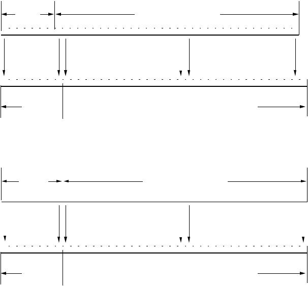
In the fractional mode, the 32-bit P output is format adjusted, that is, signextended and shifted one bit to the left before being added to MR. For example, bit 31 of P lines up with bit 32 of MR (which is bit 0 of MR2) and bit 0 of P lines up with bit 1 of MR (which is bit 1 of MR0). The LSB is zerofilled. The fractional multiplier result format is shown in Figure 2.7.
In the integer mode, the 32-bit P register is not shifted before being added to MR. Figure 2.8 shows the integer-mode result placement.
The mode is selected by bit 4 of the mode status register (MSTAT). If this bit is a 1, the integer mode is selected. Otherwise, the fractional mode is selected. In either mode, the multiplier output P is fed into a 40-bit adder/ subtracter which adds or subtracts the new product with the current contents of the MR register to form the final 40-bit result R.
2 – 16
Computational Units 2
|
|
P SIGN |
|
|
|
|
|
|
|
|
|
|
|
|
|
|
|
MULTIPLIER P OUTPUT |
|
|
|
|
|
|
|
|
|
|
|
|||||||||
|
|
|
|
|
|
|
|
|
|
|
|
|
|
|
|
|
|
|
|
|
|
|
|
|
|
|
|
|
|
|
|
|
|
|
|
|
|
|
31 |
31 |
31 |
31 |
31 |
31 |
31 |
31 |
30 |
29 |
28 |
27 |
26 |
25 |
24 |
23 |
22 |
21 |
20 |
19 |
18 |
17 |
16 |
15 |
14 |
13 |
12 |
11 |
10 |
9 |
8 |
7 |
6 |
5 |
4 |
3 |
2 |
1 |
0 |
|
|
|
|
|
|
|
|
|
|
|
|
|
|
|
|
|
|
|
|
|
|
|
|
|
|
|
|
|
|
|
|
|
|
|
|
|
|
|
7 |
6 |
5 |
4 |
3 |
2 |
1 |
0 |
15 |
14 |
13 |
12 |
11 |
10 |
9 |
8 |
7 |
6 |
5 |
4 |
3 |
2 |
1 |
0 |
15 |
14 |
13 |
12 |
11 |
10 |
9 |
8 |
7 |
6 |
5 |
4 |
3 |
2 |
1 |
0 |
|
|
|
|
|
|
|
|
|
|
|
|
|
|
|
|
|
|
|
|
|
|
|
|
|
|
|
|
|
|
|
|
|
|
|
|
|
|
|
|
MR2 
 MR1
MR1 
 MR0
MR0
Figure 2.7 Fractional Multiplier Result Format
|
|
|
P SIGN |
|
|
|
|
|
|
|
|
|
|
|
|
|
|
|
MULTIPLIER P OUTPUT |
|
|
|
|
|
|
|
|
|
|
|
|
|||||||||
|
|
|
|
|
|
|
|
|
|
|
|
|
|
|
|
|
|
|
|
|
|
|
|
|
|
|
|
|
|
|
|
|
|
|
|
|
|
|
|
|
31 |
31 |
31 |
31 |
31 |
|
31 |
31 |
31 |
31 |
30 |
29 |
28 |
27 |
26 |
25 |
24 |
23 |
22 |
21 |
20 |
19 |
18 |
17 |
16 |
15 |
14 |
13 |
12 |
11 |
10 |
9 |
8 |
7 |
6 |
5 |
4 |
3 |
2 |
1 |
0 |
|
|
|
|
|
|
|
|
|
|
|
|
|
|
|
|
|
|
|
|
|
|
|
|
|
|
|
|
|
|
|
|
|
|
|
|
|
|
|
|
|
7 |
6 |
5 |
4 |
3 |
2 |
1 |
0 |
15 |
14 |
13 |
12 |
11 |
10 |
9 |
8 |
7 |
6 |
5 |
4 |
3 |
2 |
1 |
0 |
15 |
14 |
13 |
12 |
11 |
10 |
9 |
8 |
7 |
6 |
5 |
4 |
3 |
2 |
1 |
0 |
|
|
|
|
|
|
|
|
|
|
|
|
|
|
|
|
|
|
|
|
|
|
|
|
|
|
|
|
|
|
|
|
|
|
|
|
|
|
|
|
MR2 
 MR1
MR1 
 MR0
MR0
Figure 2.8 Integer Multiplier Result Format
2 – 17
2 Computational Units
2.3.2.2 Input Formats
To facilitate multiprecision multiplications, the multiplier accepts X and Y inputs represented in any combination of signed twos-complement format and unsigned format.
X input |
|
Y input |
signed |
x |
signed |
unsigned |
x |
signed |
signed |
x |
unsigned |
unsigned |
x |
unsigned |
The input formats are specified as part of the instruction. These are dynamically selectable each time the multiplier is used.
The (signed x signed) mode is used when multiplying two signed single precision numbers or the two upper portions of two signed multiprecision numbers.
The (unsigned x signed) and (signed x unsigned) modes are used when multiplying the upper portion of a signed multiprecision number with the lower portion of another or when multiplying a signed single precision number by an unsigned single precision number.
The (unsigned x unsigned) mode is used when multiplying unsigned single precision numbers or the non-upper portions of two signed multiprecision numbers.
2.3.2.3 MAC Input/Output Registers
The sources of MAC input and output are:
Source for |
Source for |
Destination for |
X input port |
Y input port |
R output port |
MX0, MX1 |
MY0, MY1 |
MR (MR2, MR1, MR0) |
AR |
MF |
MF |
MR0, MR1, MR2 |
|
|
SR0, SR1 |
|
|
2.3.2.4 MR Register Operation
As described, and shown on the block diagram, the MR register is divided into three sections: MR0 (bits 0-15), MR1 (bits 16-31), and MR2 (bits 3239). Each of these registers can be loaded from the DMD bus and output to the R bus or the DMD bus.
2 – 18
Computational Units 2
The 8-bit MR2 register is tied to the lower 8 bits of these buses. When MR2 is output onto the DMD bus or the R bus, it is sign extended to form a 16bit value. MR1 also has an automatic sign-extend capability. When MR1 is loaded from the DMD bus, every bit in MR2 will be set to the sign bit (MSB) of MR1, so that MR2 appears as an extension of MR1. To load the MR2 register with a value other than MR1’s sign extension, you must load MR2 after MR1 has been loaded. Loading MR0 affects neither MR1 nor MR2; no sign extension occurs in MR0 loads.
2.3.2.5 MAC Overflow And Saturation
The adder/subtracter generates an overflow status signal (MV) which is loaded into the processor arithmetic status (ASTAT) every time a MAC operation is executed. The MV bit is set when the accumulator result, interpreted as a twos-complement number, crosses the 32-bit (MR1/MR2) boundary. That is, MV is set if the upper nine bits of MR are not all ones or all zeros.
The MR register has a saturation capability which sets MR to the maximum positive or negative value if an overflow or underflow has occurred. The saturation operation depends on the overflow status bit (MV) in the processor arithmetic status (ASTAT) and the MSB of the MR2 register. The following table summarizes the MR saturation operation.
MV |
MSB of MR2 |
MR contents after saturation |
|
0 |
0 or 1 |
no change |
|
1 |
0 |
00000000 0111111111111111 1111111111111111 |
full-scale positive |
1 |
1 |
11111111 1000000000000000 0000000000000000 |
full-scale negative |
Table 2.3 Effect Of MAC Saturation Instruction
Saturation in the MAC is an instruction rather than a mode as in the ALU. The saturation instruction is intended to be used at the completion of a string of multiplication/accumulations so that intermediate overflows do not cause the accumulator to saturate.
Overflowing beyond the MSB of MR2 should never be allowed. The true sign bit of the result is then irretrievably lost and saturation may not produce a correct value. It takes more than 255 overflows (MV type) to reach this state, however.
2 – 19