

Computational Units 2
When the ALU saturation mode is used, only the AR register saturates; if the AF register is the destination, wrap-around will occur but the flags will reflect the saturated result.
2.2.6ALU Overflow Latch Mode
The ALU overflow latch mode, enabled by setting bit 2 in the mode status register (MSTAT), causes the AV bit to “stick” once it is set. In this mode, when an ALU overflow occurs, AV will be set and remain set, even if subsequent ALU operations do not generate overflows. In this mode, AV can only be cleared by writing a zero to it directly from the DMD bus.
2.2.7Division
The ALU supports division. The divide function is achieved with additional shift circuitry not shown in Figure 2.2. Division is accomplished with two special divide primitives. These are used to implement a nonrestoring conditional add-subtract division algorithm. The division can be either signed or unsigned; however, the dividend and divisor must both be of the same type. Appendix B details various exceptions to the normal division operation as described in this section.
A single-precision divide, with a 32-bit dividend (numerator) and a 16-bit divisor (denominator), yielding a 16-bit quotient, executes in 16 cycles. Higher and lower precision quotients can also be calculated. The divisor can be stored in AX0, AX1 or any of the R registers. The upper half of a signed dividend can start in either AY1 or AF. The upper half of an unsigned dividend must be in AF. The lower half of any dividend must be in AY0. At the end of the divide operation, the quotient will be in AY0.
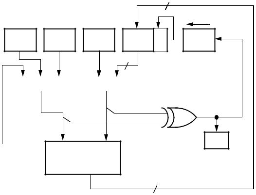
The first of the two primitive instructions “divide-sign” (DIVS) is executed at the beginning of the division when dividing signed numbers. This operation computes the sign bit of the quotient by performing an exclusive-OR of the sign bits of the divisor and the dividend. The AY0 register is shifted one place so that the computed sign bit is moved into the LSB position. The computed sign bit is also loaded into the AQ bit of the arithmetic status register. The MSB of AY0 shifts into the LSB position of AF, and the upper 15 bits of AF are loaded with the lower 15 R bits from the ALU, which simply passes the Y input value straight through to the R output. The net effect is to left shift the AF-AY0 register pair and move the quotient sign bit into the LSB position. The operation of DIVS is illustrated in Figure 2.3 (on the next page).
2 – 9
2 Computational Units
15
LEFT SHIFT
L
AX0 AX1 AY1 AF S  AY0
AY0
B
16 LOWER DIVIDEND
MUX |
|
MUX |
|
|
|
|
|
UPPER |
|
|
DIVIDEND |
|
|
MSB |
|
DIVISOR |
MSB |
|
|
|
|
X |
AQ |
R-BUS |
Y |
|
|
|
ALU |
|
|
R = PASS Y |
|
|
15 LSBs |
Figure 2.3 DIVS Operation
When dividing unsigned numbers, the DIVS operation is not used. Instead, the AQ bit in the arithmetic status register (ASTAT) should be initialized to zero by manually clearing it. The AQ bit indicates to the following operations that the quotient should be assumed positive.
The second division primitive is the “divide-quotient” (DIVQ) instruction which generates one bit of quotient at a time and is executed repeatedly to compute the remaining quotient bits. For unsigned single precision divides, the DIVQ instruction is executed 16 times to produce 16 quotient bits. For signed single precision divides, the DIVQ instruction is executed 15 times after the sign bit is computed by the DIVS operation. DIVQ instruction shifts the AY0 register left by one bit so that the new quotient bit can be moved into the LSB position. The status of the AQ bit generated from the previous operation determines the ALU operation to calculate the partial remainder. If AQ = 1, the ALU adds the divisor to the partial remainder in AF. If AQ = 0, the ALU subtracts the divisor from the partial remainder in AF. The ALU output R is offset loaded into AF just as with the DIVS operation. The AQ bit is computed as the exclusive-OR of the
2 – 10
Computational Units 2
divisor MSB and the ALU output MSB, and the quotient bit is this value inverted. The quotient bit is loaded into the LSB of the AY0 register which is also shifted left by one bit. The DIVQ operation is illustrated in Figure 2.4.
15
LEFT SHIFT
L
AX0 AX1 AF S  AY0
AY0
B
LOWER
DIVIDEND
PARTIAL
REMAINDER
MUX  16
16
DIVISOR MSB
R-BUS |
X |
Y |
AQ |
|
|
ALU |
|
R=Y+X IF AQ=1
R=Y-X IF AQ=0
1 MSB
15 LSBs
Figure 2.4 DIVQ Operation
The format of the quotient for any numeric representation can be determined by the format of the dividend and divisor. Let NL represent the number of bits to the left of the binary point, and NR represent the number of bits to the right of the binary point of the dividend; DL represent the number of bits to the left of the binary point, and DR represent the number of bits to the right of the binary point of the divisor; then the quotient has NL–DL+1 bits to the left of the binary point and NR– DR–1 bits to the right of the binary point.
2 – 11
2 Computational Units
Some format manipulation may be necessary to guarantee the validity of the quotient. For example, if both operands are signed and fully fractional (dividend in 1.31 format and divisor in 1.15 format) the result is fully fractional (in 1.15 format) and therefore the dividend must be smaller than the divisor for a valid result.
To divide two integers (dividend in 32.0 format and divisor in 16.0 format) and produce an integer quotient (in 16.0 format), you must shift the dividend one bit to the left (into 31.1 format) before dividing. Additional discussion and code examples can be found in the handbook Digital Signal Processing Applications Using the ADSP-2100 Family, Volume 1.
Dividend BBBBB.BBBBBBBBBBBBBBBBBBBBBBBBBBB
NL bits |
NR bits |
Divisor BB.BBBBBBBBBBBBBB
DL bits |
DR bits |
Quotient BBBB.BBBBBBBBBBBB
(NL–DL+1) bits |
(NR–DR–1) bits |
Figure 2.5 Quotient Format
The algorithm overflows if the result cannot be represented in the format of the quotient as calculated above or when the divisor is zero or less than the dividend in magnitude.
2 – 12