- •Table of Contents
- •1. Communication Capabilities
- •1.1 System Configurations
- •1.1.1 Send an SMS Message to a Mobile Phone
- •1.1.2 Receive the Short Message from a PC and phone
- •1.1.3 Detect The Phone Ringing
- •1.1.5 Program/monitor from remote PC using a GSM Modem
- •1.1.6 Program/Monitor from remote PC using a standard Modem
- •1.1.7 RS - 232C Straight Cable
- •1.2 Dedicated Protocol Communication
- •1.2.1 Dedicated Protocol Configuration
- •2. SMS/SMR/CD Fanctions and the Modem Setting
- •2.1 Set the parameters of the GSM modem from VLS software.
- •2.1.1 GSM & Serial Communication Dialog Box
- •2.1.2 The “Initialize Modem...” Setting
- •2.2 The GSM/SMS Function Block
- •2.2.1 The Short Message Service (SMS)
- •2.2.2 SMS Setting Dialog Box
- •2.3 The SMR Function Block
- •2.3.1 The Short Message Receiving (SMR)
- •2.4 The CD Function Block
- •2.4.1 Call Detect (CD)
- •2.5 Set GSM Modem Parameters from the Front Panel Keys
- •2.5.1 ComFormat
- •2.5.2 The GSM Init Command (GSM Initialization Command)
- •2.5.3 Pin Code
- •2.5.5 GSM Status
- •2.6 Characters in GSM Protocol
- •2.6.1 The GSM Character Table
- •2.6.2 French GSM Characters
- •2.6.3 Italian GSM Characters
- •2.7.1 SMS Function Block Example
- •2.7.2 SMR Function Block Example
- •2.7.3 CD Function Block Example
- •3. Remote Access
- •3.1 GSM Remote Access
- •3.1.1 Set Parameters from the VLS software
- •3.1.2 GSM & Serial Communication Dialog Box
- •3.1.3 GSM Modem Settings
- •3.1.4 The GSM Init Command (GSM Initialization Command)
- •3.1.5 Command Setting
- •3.1.6 Delay Time
- •3.1.7 GSM Remote Command
- •3.1.8 The PIN Code
- •3.2 Standard Modem Remote Access
- •3.3 Set Parameters from VLS software
- •3.3.1 GSM & Serial Communication Dialog Box
- •3.3.2 Standard Modem Settings
- •3.3.3 The Command Setting
- •3.3.4 The Delay Time Setting
- •3.3.5 Standard Preconfigured Modems
- •4. SMS Messaging Diagnostics
- •4.1 Check points for Mobile Phone Communication Problems
- •4.3 GSM Status
- •4.3.1 GSM Status
- •4.3.2 CME Error
- •4.3.3 CMS Error
- •4.3.4 Signal Strength (Sigstreng)
- •5. Computer Link - Dedicated Protocol
- •5.1 Data Flow by Link
- •5.2 Configuration Diagram
- •5.3 How to read Dedicated Protocol
- •6.1 GSM and Serial Communication Setting
- •6.2 Function Blocks
- •6.3 Settings for Dedicated Protocol - Front Panel Keys
- •6.3.1 Top Menu Setting/Serial Com Settings
- •6.3.2 The “Other Com” Settings
- •6.3.3 The Comformat (Communication Format)
- •6.3.4 Data Length
- •6.3.5 Parity
- •6.3.6 Stop Bits
- •6.3.7 Baud Rate
- •6.3.8 Default
- •6.3.9 Station Number
- •6.3.10 Link Block
- •6.3.11 Function Block Bit and Word Data
- •7. The Command String
- •7.1 Format “A”
- •7.2 Format “B” Message
- •7.3 Control Protocol elements
- •7.3.1 Control Codes
- •7.3.2 No. of Communication Bytes
- •7.3.3 Format Number
- •7.3.4 Station Number
- •7.3.5 Command
- •7.3.6 Number of Devices
- •7.3.7 Device Code
- •7.3.8 Device Number
- •7.3.9 Device Status
- •7.3.10 Sum Check
- •7.3.11 Error Codes
- •7.4 Communication Timing Chart
- •7.4.1 Read/Write Data from the Controller
- •7.4.2 Communication Time
- •7.5 Character Area Data Transmission
- •7.5.1 Read Data Transmission
- •7.5.2 Write Data Transmission
- •7.5.3 Time Switch Data Transmission
- •7.6 Commands
- •7.6.1 Communication Line Check
- •7.6.2 Read Command
- •7.6.3 Write Command
- •7.6.4 Remote RUN/STOP Operation
- •7.6.5 Time Switch Settings
- •7.6.6 VLS Time Switch Settings (Sample)
- •7.6.7 RTC Read Command
- •7.6.8 RTC Write Command
- •7.7 Sample Visual Basic program
- •8. Dedicated Protocol Error Diagnostics
- •8.1 Check points for Dedicated Protocol
α2 Simple Application Controllers |
The Command String 7 |
7.4Communication Timing Chart
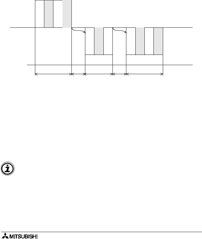
The communication time for α2 Series dedicated protocol is represented by the diagram below. The communication time is identical for Read and Write operations. Thus, only one diagram has been used to demonstrate the possible delaytimes for sending and receiving 8-bit binary messages.
7.4.1Read/Write Data from the Controller
Format B READ/WRITE operation
|
STX |
ETX |
|
|
|
|
|
Computer |
|
|
|
|
|
|
Communication |
02H |
03H |
|
|
|
|
Line |
|
α2 Controller |
|
|
STX |
|
STX |
ETX |
|
|
|
|
! |
|
|||
|
|
|
02H |
21H |
02H |
03H |
|
|
|
T0 |
Tw |
T1 |
TP |
T2 |
Time Chart |
|
|
Line |
|||||
|
|
|
|
|
|
|
7.4.2Communication Time
The calculation performed below are a guide to the approximate communication timing for dedicated protocol.
T0,T1,T2 = 1/Baud Rate x No. of bits in 1 character x No. of Characters
= 1/9600 x [1 (Startbit) x 8 (datalength) x 0 (parity none) x 1 (stopbit] x No. of characters
TP = Process Time *1 maximum time of 2.5s
Tw = 5ms + maximum of 1 scan time maximum time of 2.5s
Note:
*1 Process Time - Represents the duration needed for the α2 Series Controller to process with either READING the intended device or WRITING to the intended devices specified in the Command String. 1scan time + 5ms is the minimum time used for the Process Time.
7 - 15