


α2 Simple Application Controllers |
The Command String 7 |
7.The Command String
The following chapter explains the structure of both types of dedicated protocol format for the α2 Series Controller. The 8-bit binary protocol is available in two different formats:
1 ) Format A
2 ) Format B
The Dedicated Protocol is based on a PC or Peripheral device sending messages to the α2 controller and in return receiving replies to those commands. The string of data that accomplishes these tasks is called the Command String. The Command String can be used to check the communication line, read/write from/to internal bit/word data, perform remote Run/ Stop operation with the controller, and to edit Time Switch data. The data contained in the Command String varies with the type of action to be accomplished.
Two formats have been designed to carry the data - Format “A” for simple Communication line checks and Format “B” for the more involved data processing instructions. The information to construct and read Command Strings is explained in this chapter.
Communication between the computer and the α2 Series Controller is handled using interrupts. The Transmit/Receive process is completed after the last operation has been completed in the Function block sequence order. Refer to the Communication Timing section for further information concerning response delay time.
Notes:
Communication requirements
a ) Power to the α2 Series Controller
b ) Switching the Serial Com mode to Dedicated Protocol. Using the front panel keys select “Serial Com” from the “others...” menu. Select “Other Com” then proceed to cycle the power to accept the setting. Or, using AL-VLS/WIN-E please refer to Chapter 6.
Communication Settings
a ) |
Baud Rate: |
9600bps |
b ) |
Datalength: |
8bits |
c ) |
Parity: |
None |
d ) |
Stop bit: |
1 |
e ) |
Synchronous method: |
Half-Duplex |
f ) |
Framing, Overrun or communication errors will occur if the default communication |
|
|
dedicated protocol setting have not been entered. Using the front panel keys, select |
|
“Serial Com” from the “others...” menu. Select “Other Com” and adjust the “ComFormat, Station No. and Link Block” accordingly. Refer to Chapter 6 for detailed information concerning Front panel screen. However, the user can also set the default communication dedicated protocol settings from the VLS software.
7 - 1

α2 Simple Application Controllers |
The Command String 7 |
Section 7.1 and 7.2 describe protocol elements used with Format A and B. Refer to section 7.3 for detailed explanation concerning all dedicated protocol elements within both types of formats. Refer to section 7.6 for detailed information concerning α2 Series Commands.
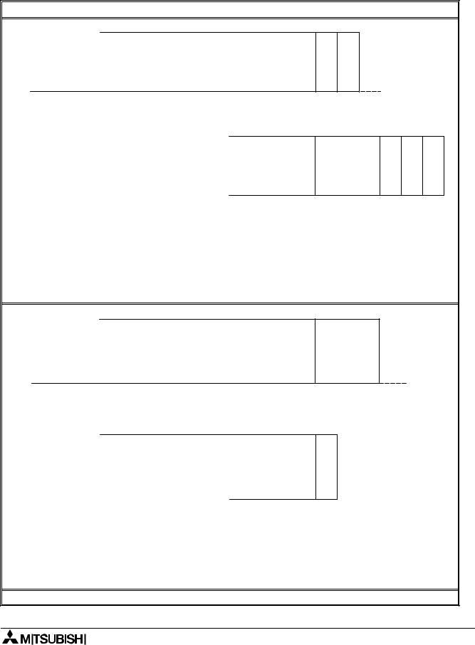
7.1Format “A”
Table 7.1: 1.1 Format A message structure
|
|
|
|
|
|
Control Protocol |
|
|
|
|
|
|
|
|
||||
|
|
|
|
|
|
|
|
|
|
|
|
|
|
|
|
|
|
|
|
|
|
|
|
|
|
|
|
|
|
|
|
|
|
|
|
|
|
|
|
S |
commNo. |
bytes |
|
FormatNo. |
|
StationNo. |
E |
|
|
|
|
|
|
|
|
|
|
|
T |
|
|
|
|
|
|
N |
|
|
|
|
|
|
|
|
|
|
|
X |
|
|
|
|
|
|
Q |
|
|
|
|
|
|
|
|
|
|
Computer |
|
|
|
|
|
|
|
|
|
|
|
|
|
|
|
|
|
|
|
|
|
|
|
|
|
|
|
|
|
|
|
|
|
|
|
|
CHECKLINE |
α2 Controller |
|
|
|
|
|
|
|
S |
|
commNo. |
bytes |
|
FormatNo. |
|
StationNo. |
||
|
|
|
|
|
|
|
|
|
|
|
|
|||||||
|
|
|
|
|
|
|
|
|
|
T |
|
|
|
|
|
|
|
|
|
|
|
|
|
|
|
|
|
|
X |
|
|
|
|
|
|
|
|
|
|
|
|
|
|
|
|
|
|
|
|
|
|
|
or |
|
|
|
|
|
|
|
|
|
|
|
|
|
|
|
|
|
|
|
|
||
|
|
|
|
|
|
|
|
|
|
S |
|
commNo. |
bytes |
|
FormatNo. |
|
StationNo. |
|
|
|
|
|
|
|
|
|
|
|
|
|
|
||||||
|
|
|
|
|
|
|
|
|
|
T |
|
|
|
|
|
|
|
|
|
|
|
|
|
|
|
|
|
|
X |
|
|
|
|
|
|
|
|
|
|
|
|
|
|
|
|
|
|
|
|
|
|
|
|
|
|
|
|
|
|
|
|
|
|
FORMAT A |
|
|
|
|
|
|
|
|
|||
|
|
|
|
|
|
|
|
|
|
|
|
|
|
|
||||
Format A LINE CHECK mode |
|
|
|
|
|
|
|
|
|
|
|
|
|
|
|
|
||
|
|
|
|
|
|
|
|
|
|
|
|
|
|
|
|
|
||
|
|
|
|
|
|
|
|
Control C ode |
|
|
|
|
|
|
|
|
||
|
|
|
|
|
|
|
|
|
||||||||||
|
|
|
|
|
No. of C om m unication bytes |
|
|
|||||||||||
|
|
|
|
|
|
|
|
Form at N o. |
|
|
|
|
|
|
|
|
||
|
|
|
|
|
|
|
|
Station N o. |
|
|
|
|
|
|
|
|
||
|
|
|
|
|
|
|
|
Control C ode |
|
|
|
|
|
|
|
|
||
A
C
K
N |
Code |
|
A |
Error |
|
K |
||
|
||
|
|
7 - 2
α2 Simple Application Controllers |
The Command String 7 |
7.2Format “B” Message
Table 7.2: Format B message structure
|
|
|
|
|
|
|
|
|
|
|
|
|
|
|
|
|
|
|
|
|
|
|
|
|
|
|
|
|
|
|
|
|
|
|
|
|
Control Protocol |
|
|
|
|
|
|
|
||||||||||||||||||||||||
|
Transmit |
|
|
|
|
|
|
|
|
|
|
|
|
|
|
|
|
|
|
|
|
|
|
|
|
|
|
|
|
|
|
|
|
|
|
|
|
|
|
|
|
|
|
|
|
|
|
|
|
|
||||||||||||||||||
|
|
|
|
|
|
|
|
|
|
|
|
|
|
|
|
|
|
|
|
|
|
|
|
|
|
|
|
|
|
|
|
|
|
|
|
|
|
|
|
|
|
|
|
|
|
|
|
|
|
|||||||||||||||||||
|
Computer |
|
S |
|
|
commNo. bytes |
|
FormatNo. |
|
|
StationNo. |
|
Command |
|
ofNo. devices |
|
codeDevice |
|
DeviceNo. |
(LB) |
|
DeviceNo. (HB) |
|
E |
||||||||||||||||||||||||||||||||||||||||||||
|
|
|
|
|
|
|
|
|
|
|
|
|
||||||||||||||||||||||||||||||||||||||||||||||||||||||||
|
|
|
|
|
|
|
|
|
|
|
|
|
|
|
|
|
|
|
|
|
T |
|
|
|
|
|
|
|
|
|
|
|
|
|
|
|
|
|
|
|
|
|
|
|
|
|
|
|
|
|
|
|
|
|
|
|
|
|
|
|
|
|
|
|
|
|
|
T |
|
|
|
|
|
|
|
|
|
|
|
|
|
|
|
|
|
|
|
|
|
X |
|
|
|
|
|
|
|
|
|
|
|
|
|
|
|
|
|
|
|
|
|
|
|
|
|
|
|
|
|
|
|
|
|
|
|
|
|
|
|
|
|
|
|
|
|
|
X |
|
α2 Controller |
|
|
|
|
|
|
|
|
|
|
|
|
|
|
|
|
|
|
|
|
|
|
|
|
|
|
|
|
|
|
|
|
|
|
|
|
|
|
|
|
|
|
|
|
|
|
|
|
|
||||||||||||||||||
|
|
|
|
|
|
|
|
|
|
|
|
|
|
|
|
|
|
|
|
|
|
|
|
|
|
|
|
|
|
|
|
|
|
|
|
|
|
|
|
|
|
|
|
|
|
|
|
|
|
|||||||||||||||||||
|
Receive |
|
|
|
|
|
|
|
|
|
|
|
|
|
|
|
|
|
|
|
|
|
|
|
|
|
|
|
|
|
|
|
|
|
|
|
|
|
|
|
|
|
|
|
|
|
|
|
|
|
||||||||||||||||||
READ |
|
|
|
|
|
|
|
|
|
|
|
|
|
|
|
|
|
|
|
|
|
|
|
|
|
|
|
|
|
|
|
|
|
|
|
|
|
|
|
|
|
|
|
|
|
|
|
|
|
|
|
|
|
|
|
commsNo. |
bytes |
|
|
|
FormatNo. |
|
|
|
StationNo. |
|||
|
|
|
|
|
|
|
|
|
|
|
|
|
|
|
|
|
|
|
|
S |
|
commNo. |
bytes |
|
|
|
FormatNo. |
|
|
StationNo. |
|
|
|
|
Completeflag |
|
|
|
|
|
|
|
|
|
|
|
|
|
|
S |
|
|
|
|
|
|
|
|
|
|||||||||
|
|
|
|
|
|
|
|
|
|
|
|
|
|
|
|
|
|
|
|
|
T |
|
|
|
|
|
|
|
|
|
|
|
|
|
|
|
|
|
|
|
|
|
|
|
|
|
|
|
|
|
|
T |
|
|
|
|
|
|
|
|
|
|
|
|
|
|
|
|
|
|
|
|
|
|
|
|
|
|
|
|
|
|
|
|
|
|
|
|
|
X |
|
|
|
|
|
|
|
|
|
|
|
|
|
|
|
|
|
|
|
|
|
|
|
|
|
|
|
|
|
|
X |
|
|
|
|
|
|
|
|
|
|
|
|
|
|
|
|
|
|
|
|
|
|
|
|
|
|
|
|
|
|
|
|
|
|
|
|
|
|
|
|
|
|
|
|
|
|
|
|
|
|
|
|
|
|
|
|
|
|
|
|
|
|
|
|
|
|
|
|
|
|
|
|
|
|
|
|
|
|
|
|
|
|
|
|
|
|
|
|
|
|
|
|
|
|
|
|
|
|
|
|
|
|
|
|
|
|
|
|
|
|
|
|
|
|
|
or |
|
|
|
|
|
|
|
|
|
|
|
|
|
|
|
|
|
|
|
|
|
|
|
|
|
|
|
|
|
|
|
|
|
|||||
|
|
|
|
|
|
|
|
|
|
|
|
|
|
|
|
|
|
|
|
|
|
|
|
|
|
|
|
|
|
|
|
|
|
|
|
|
|
|
|
|
|
|
|
|
|
|
|
|
|
|
|
|
|
|
|
|
|
|
|
|
|
|
|
|
|
|
||
|
|
|
|
|
|
|
|
|
|
|
|
|
|
|
|
|
|
|
|
|
S |
|
commNo. |
bytes |
|
|
|
FormatNo. |
|
|
StationNo. |
|
|
|
|
N |
|
|
|
|
|
CodeError |
|
|
|
|
|
|
|
|
|
|
|
|
|
|
|
|
|
|
|
|
|
|||||
|
|
|
|
|
|
|
|
|
|
|
|
|
|
|
|
|
|
|
|
|
T |
|
|
|
|
|
|
|
|
|
|
|
|
|
|
|
A |
|
|
|
|
|
|
|
|
|
|
|
|
|
|
|
|
|
|
|
|
|
|
|
|
|
|
|
|
|
|
|
|
|
|
|
|
|
|
|
|
|
|
|
|
|
|
|
|
|
|
|
|
X |
|
|
|
|
|
|
|
|
|
|
|
|
|
|
|
K |
|
|
|
|
|
|
|
|
|
|
|
|
|
|
|
|
|
|
|
|
|
|
|
|
|
|
|
|
|
|
|
|
|
|
|
|
|
|
|
|
|
|
|
|
|
|
|
|
|
|
|
|
|
|
|
|
|
|
|
|
|
|
|
|
|
|
|
|
|
|
|
|
|
|
|
|
|
|
|
|
|
|
|
|
|
|
|
|
|
|
|
|||||||||
|
Transmit |
|
|
|
|
|
|
|
|
|
|
|
|
|
|
|
|
|
|
|
|
|
|
|
|
|
|
|
|
|
|
|
|
|
|
|
|
|
|
|
|
|
|
|
|
|
|
|
|
|
||||||||||||||||||
OPERATION |
|
|
|
|
|
|
|
|
|
|
|
|
|
|
|
|
|
|
|
|
S |
|
|
commNo. |
bytes |
|
|
|
FormatNo. |
|
|
StationNo. |
|
|
|
Command |
|
|
|
|
devicesofNo. |
|
|
|
codeDevice |
|
|
|
DeviceNo. |
(LB) |
|
|
|
DeviceNo. (HB) |
|
|
|
statusDevice |
||||||||||
|
|
|
|
|
|
|
|
|
|
|
|
|
|
|
|
|
|
|
|
|
|
|
|
|
|
|
|
|
|
|
|
|
|
|
|
|
|
|
|
|
|
|
|
|
|
|||||||||||||||||||||||
|
|
|
|
|
|
|
|
|
|
|
|
|
|
|
|
|
|
|
|
|
T |
|
|
|
|
|
|
|
|
|
|
|
|
|
|
|
|
|
|
|
|
|
|
|
|
|
|
|
|
|
|
|
|
|
|
|
|
|
|
|
|
|
|
|
|
|
|
|
|
|
|
|
|
|
|
|
|
|
|
|
|
|
|
|
|
|
|
|
|
X |
|
|
|
|
|
|
|
|
|
|
|
|
|
|
|
|
|
|
|
|
|
|
|
|
|
|
|
|
|
|
|
|
|
|
|
|
|
|
|
|
|
|
|
|
|
|
|
|
Computer |
|
|
|
|
|
|
|
|
|
|
|
|
|
|
|
|
|
|
|
|
|
|
|
|
|
|
|
|
|
|
|
|
|
|
|
|
|
|
|
|
|
|
|
|
|
|
|
|
|
||||||||||||||||||
|
|
|
|
|
|
|
|
|
|
|
|
|
|
|
|
|
|
|
|
|
|
|
|
|
|
|
|
|
|
|
|
|
|
|
|
|
|
|
|
|
|
|
|
|
|
|
|
|
|
|
|
|
|
|
|
|
|
|
|
|||||||||
|
α2 Controller |
|
|
|
|
|
|
|
|
|
|
|
|
|
|
|
|
|
|
|
|
|
|
|
|
|
|
|
|
|
|
|
|
|
|
|
|
|
|
|
|
|
|
|
|
|
|
|
|
|
||||||||||||||||||
WRITE/(RUN/STOP) |
Receive |
|
|
|
|
|
|
|
|
|
|
|
|
|
|
|
|
|
|
|
|
|
|
|
|
|
|
|
|
|
|
|
|
|
|
|
|
|
|
|
|
|
|
|
|
|
|
|
|
|
||||||||||||||||||
|
|
|
|
|
|
|
|
|
|
|
|
|
|
|
|
|
|
|
|
S |
|
|
commNo. |
bytes |
|
|
FormatNo. |
|
|
StationNo. |
|
|
Completeflag |
|
|
|
|
|
|
|
|
|
|
|
|
S |
|
|
commNo. |
bytes |
|
|
FormatNo. |
|
|
StartionNo. |
||||||||||||
|
|
|
|
|
|
|
|
|
|
|
|
|
|
|
|
|
|
|
|
|
|
|
|
|
|
|
|
|
|
|
|
|
|
|
|
|
|
|
|
|
|
|
|
|
|
|||||||||||||||||||||||
|
|
|
|
|
|
|
|
|
|
|
|
|
|
|
|
|
|
|
|
|
T |
|
|
|
|
|
|
|
|
|
|
|
|
|
|
|
|
|
|
|
|
|
|
|
|
|
|
|
|
|
|
T |
|
|
|
|
|
|
|
|
|
|
|
|
|
|
||
|
|
|
|
|
|
|
|
|
|
|
|
|
|
|
|
|
|
|
|
|
X |
|
|
|
|
|
|
|
|
|
|
|
|
|
|
|
|
|
|
|
|
|
|
|
|
|
|
|
|
|
|
X |
|
|
|
|
|
|
|
|
|
|
|
|
|
|
||
|
|
|
|
|
|
|
|
|
|
|
|
|
|
|
|
|
|
|
|
|
|
|
|
|
|
|
|
|
|
|
|
|
|
|
|
|
|
|
|
|
|
|
|
|
|
|
|
|
|
|
|
|
|
|
|
|
|
|
|
|
|
|
|
|
|
|||
|
|
|
|
|
|
|
|
|
|
|
|
|
|
|
|
|
|
|
|
|
|
|
|
|
|
|
|
|
|
or |
|
|
|
|
|
|
|
|
|
|
|
|
|
|
|
|
|
|
|
|
|
|
|
|
|
|
|
|
|
|
|
|
|
|||||
|
|
|
|
|
|
|
|
|
|
|
|
|
|
|
|
|
|
|
|
|
|
|
|
|
|
|
|
|
|
|
|
|
|
|
|
|
|
|
|
|
|
|
|
|
|
|
|
|
|
|
|
|
|
|
|
|
||||||||||||
|
|
|
|
|
|
|
|
|
|
|
|
|
|
|
|
|
|
|
|
|
S |
|
|
commNo. |
bytes |
|
|
FormatNo. |
|
|
StationNo. |
|
|
N |
|
|
|
CodeError |
|
|
|
|
|
|
|
|
|
|
|
|
|
|
|
|
|
|
|
|||||||||||
|
|
|
|
|
|
|
|
|
|
|
|
|
|
|
|
|
|
|
|
|
T |
|
|
|
|
|
|
|
|
|
|
|
|
|
|
|
A |
|
|
|
|
|
|
|
|
|
|
|
|
|
|
|
|
|
|
|
|
|
|
|
|
|
|
|
|
|
||
|
|
|
|
|
|
|
|
|
|
|
|
|
|
|
|
|
|
|
|
|
X |
|
|
|
|
|
|
|
|
|
|
|
|
|
|
|
K |
|
|
|
|
|
|
|
|
|
|
|
|
|
|
|
|
|
|
|
|
|
|
|
|
|
|
|
|
|
||
|
|
|
|
|
|
|
|
|
|
|
|
|
|
|
|
|
|
|
|
|
|
|
|
|
|
|
|
|
|
|
|
|
|
|
|
|
|
|
|
|
|
|
|
|
|
|
|
|
|
|
|
|
|
|
|
|
|
|
|
|
|
|
|
|
|
|
|
|
|
|
|
|
|
|
|
|
|
|
|
|
|
|
|
|
|
|
|
|
|
|
|
|
|
|
|
|
|
|
|
|
|
|
|
|
|
|
|
|
|
|
|
|
|
|
|
|
|
|
|
|
|
|
|
|
|
|
|
|
|
|
|
|
|
|
|
|
|
FORMAT B
Sum check code (LB) Sum check code (HB)
Command |
No. of devices |
Device status |
|
|
|
E |
checkSum |
(LB)code |
checkSum (HB)code |
T |
|
|
|
X |
|
|
|
|
|
|
|
A
C
K
E T X
Sum check code (LB) Sum check code (HB)
7 - 3

α2 Simple Application Controllers |
The Command String 7 |
Note:
1 ) Format B WRITE/(RUN/STOP) operation can produce an error code even though a standard complete flag has been sent. If the Transmit message contains the correct syntax then a complete flag will be sent, however, if the reply data is corrupt then a NAK message will be generated.
2 ) The write message string is intended for BIT data accessing, therefore, only one byte has been allocated to the Device Status setting. To write to WORD data, 2 bytes must be allocated to the Device setting. Thus, caution in setting the No. of communication bytes and the sum code check must be taken.
Read/Write operation for Format B follows a different structure to Format A. Format B uses a more complex string to access internal devices. However, the write operation contains the Device Status parameter used to indicate the ON/OFF state of the intended device.
Time Switch settings follow Format B protocol, however, the structure and content of the string differs from the standard READ/WRITE mode operation. Refer to section 7.6.5 for further detailed information concerning Time Switch settings for Format B.
Format B READ Mode Format B WRITE mode (BIT)
Control C ode
No. of C om m unication bytes
Form at N o.
Station N o.
Com m and
No. of devices
Device C ode
Device N o. (LB)
Device N o. (HB)
Control C ode
Sum Check (LB)
Sum Check (HB)
Control C ode
No. of C om m unication bytes
Form at N o.
Station N o.
Com m and
No. of devices
Device C ode
Device N o. (LB)
Device N o. (HB)
Device Status
Control C ode
Sum Check (LB)
Sum Check (HB)
7 - 4