

α2 Simple Application Controllers |
Remote Access 3 |
3.Remote Access
The settings required to send SMS packets via a GSM modem or to set up the α2 controller for remote access can be accomplished with the front panel keys. It is possible to perform remote operations with a standard modem but it is not possible to send SMS packets.
Certain parameters in the α2 controller and GSM modem must be set in order to perform Remote Access from an external PC. These parameters can be set quickly and easily in the VLS software or with slightly more effort from the front panel keys.
The equipment and configuration for this style of communication is listed in section 1.1 of this manual.
3.1GSM Remote Access
3.1.1Set Parameters from the VLS software
The Visual Logic Software (VLS) provides the easiest method to set the parameters and download them to the controller. The communication method is the first setting necessary in the VLS software.
Open or start a new program and then choose “Option” on the menu bar. Click “GSM and Serial Communication” to open the dialog box necessary to begin parameter input.
3 - 1
α2 Simple Application Controllers |
Remote Access 3 |
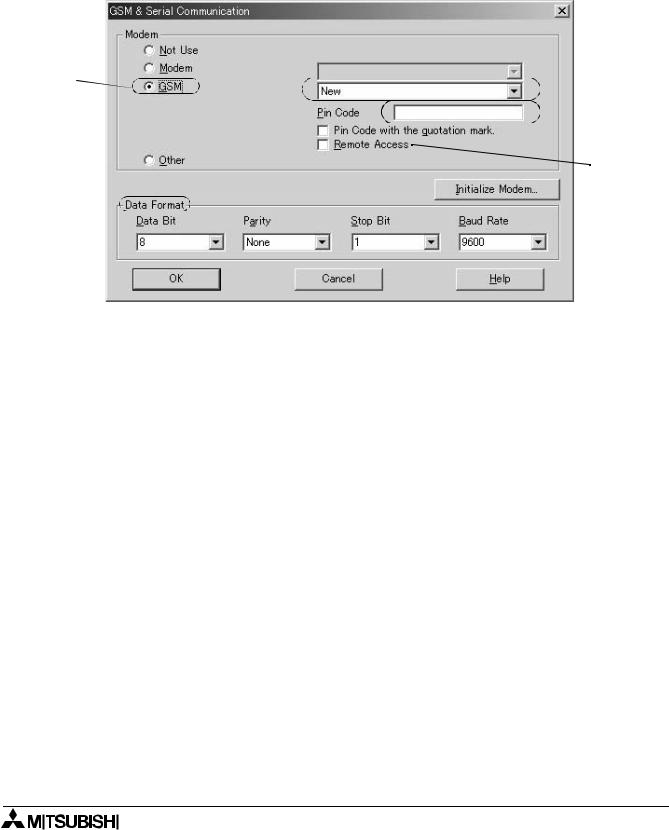
3.1.2GSM & Serial Communication Dialog Box
The “GSM and Serial Communication” dialog box is used to set the equipment and communication type for the controller. A short explanation of each parameter is given below.
In order to obtain remote access using a GSM modem, the GSM circle must be clicked, the Remote Access box checked, and the GSM Pin Code entered.
A) |
(G |
|
|
|
(B |
 (C (D
(C (D 
 (E
(E
F)
A)GSM - This setting is used when a GSM modem will be connected either to send an SMS message or for Remote Access communication.
B)Pin Code - The GSM PIN (Personal Identification Numbers for use of GSM)
C)Pin Code with the quotation mark - GSM SIM PIN is send to the modem in quotation marks (necessary for Sony Ericsson GSM modem)
D)Remote Access - Setting to allow GSM modems to have Remote Access capability.
E)Initialize Modem - AT Command used to initialize a modem.
F)Data Format - Settings for Com ports and message protocol.
G)Registered GSM Modems - List of available GSM modems for the user to choose from, however, this list can be extended by writing to the GSM.ini file.
Refer to the section 2.1 for further detailed information concerning VLS settings for remote access using GSM.
3 - 2
α2 Simple Application Controllers |
Remote Access 3 |
3.1.3GSM Modem Settings
The numerous parameters and options for using the GSM modem can be set using the front panel keys although this procedure is significantly more difficult than using the AL-PCS/WIN-E software.
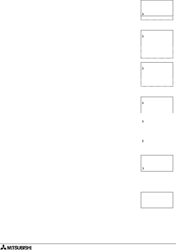
To begin the process from the Top Menu, scroll down to “Others/Serial Com/GSM” and view the options shown at right.
S e r i a l C o m N o t U s e
M o d e m G S M
O t h e r C o m
GSM
C omF o r ma t
GSM |
I n i t |
GSM |
R emo t e |
P I N |
C o d e |
S e t |
SMS |
GSM |
S t a t u s |
Comformat (Communication Format)
Upon entering the GSM option, the ComFormat dialog will be the first option. The Comformat allows the user to set the communication settings for Data Length, Parity, Stop Bit, and Baudrate.
Scroll to the setting to be adjusted.
Data Length
Select a Data length send parameter of 7 or 8 bits.
Parity
Select from three options for Parity - None, Odd or Even.
Stop Bits
Choose the number of stop bits - 1 bit or 2 bits.
Baud Rate
Select the baud rate - 9600 or 19200 bps.
C omF o r ma t
D a t a L e n g t h
P a r i |
t y |
S t o p |
b i t |
B a u d r a t e |
|
D e f a u l t |
|
D a t a L e n g t h
8 |
b i |
t s |
|
7 |
b i |
t s |
|
|
|
|
|
|
|
|
|
P a r |
i |
t y |
|
N o n e |
|
||
O d d |
|
|
|
E v e n |
|
||
|
|
|
|
S t o p |
|
b i t |
|
1 b i |
t |
|
|
2 b i |
t s |
||
|
|
|
|
Default
The controller can be returned to the default communication settings -
DataLength = 8 bits; Parity = None; Stop Bits = 1; and Baud Rate = 9600 bps - by pressing “OK” when the pointer is on the Default option.
3.1.4The GSM Init Command (GSM Initialization Command)
The GSM modem must have an initialization command string. After choosing the “GSM Init” option, the Command and Delay Time settings will appear.
GSM I n i t
 C omma n d
D e l a y T i me
3 - 3
α2 Simple Application Controllers |
Remote Access 3 |
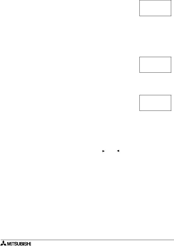
3.1.5Command Setting
Choose “Command” to enter the AT command. Details for the AT command should be included in the literature of the modem.
GSM |
I n i t 0 1 |
C omma n d |
|
[ A |
] |
< = > ?@A BCDE
Enter the string by choosing the characters with the “  ” and “
  ”
”
arrows. When a desired letter is shown onscreen, move to the right by pressing the “  ” key. The character will remain in the previous cursor space. Do not press the “OK” key until the command has been entered in its entirety.
Move to the left for editing purposes with the “ ” key.
3.1.6Delay Time
The Delay Time Setting will delay the transmission of the initialization command while the modem completes its power up.
Use the “+” key to increment the value and the “-” to decrement the value within the range of 0 - 10 seconds. Enter the value by pressing the “OK” key.
GSM I n i t
D e l a y T i me 0 s
3.1.7GSM Remote Command
Remote access from a computer running the VLS software is allowed when “Permit” is chosen.
SMS packets cannot be sent under the “Permit” setting but can be sent when “Forbid” is used.
GSM R emo t e  F o r b i d
P e r m i t
3.1.8 The PIN Code
Enter the PIN Code |
|
|
P I N C o d e |
||
It is necessary to enter a PIN code received from the Service Provider |
||
S e t u p |
||
when the α2 controller is used to send SMS packets. Use the “+” and |
[ ] |
|
“-” keys to choose the digits of the code and the “ ” and “ ” keys to |
|
|
|
||
move to adjoining digits. |
|
SIM PIN setup [“****”] or [****] can be activated and deactivated by the cursor U and cursor V soft key.
All the numbers must be set to an integer value or a PIN Code Error will be received. Press the “OK” or “ESC” key to return to the PIN Code entry display. Finish entering all integer values into all four digits and press “OK” to enter the code.
Cancel the PIN Code
To Cancel an existing PIN code, enter the PIN Code option and confirm with the “OK” button the intent to Cancel the code. The PIN Code does not have to be entered in order to Cancel the code.
P I N |
C o d e |
|
C a n c e |
l |
|
O K |
o r |
E S C |
|
|
|
Use the “ESC” button to return to the GSM menu.
3 - 4