


α2 Simple Application Controllers |
Computer Link - Dedicated Protocol 5 |
5.3How to read Dedicated Protocol
Format A for computer link is used for checking the communication line between the computer and the α2 Series Controller. Thus, the read/write format for the structure of the string is identical. Refer to section 7.1 for detailed 8-bit binary string structure.
Format A: Communication Line Check
|
S |
|
E |
|
|
|
|
|
T |
|
N |
|
|
|
|
Computer |
X |
|
Q |
|
|
|
|
|
|
|
|
|
|
|
|
α2 Controller |
|
|
|
S |
|
A |
|
|
|
|
|
T |
|
C |
|
|
|
|
|
X |
|
K |
|
|
|
|
|
|
|
|
|
Format B for computer link is generally used for reading/writing to all internal devices, reading/ writing to function block bit/word data, run/stop mode and configuring the Time Switch settings. Thus, the command string is more complex compared to the Format A equilvalent.Refer to section 8.3 for detailed 8-bit binary string structure.
Format B: Computer READS from the α2 Series Controller
|
S |
|
E |
|
|
|
|
|
|
|
T |
|
T |
|
|
|
|
|
|
Computer |
X |
|
X |
|
|
|
|
|
|
α2 Controller |
|
|
|
|
S |
|
Complete flag |
|
S |
|
|
|
|
|
|
||||
|
|
|
|
|
T |
|
|
|
T |
|
|
|
|
|
X |
|
|
|
X |
|
|
|
|
|
|
|
|
|
|
Format B: Computer WRITES to the α2 Series Control
E T X
|
S |
|
E |
|
|
|
T |
|
T |
|
|
Computer |
X |
|
X |
|
|
α2 Controller |
|
|
|
|
S |
|
|
|
|
||
|
|
|
|
|
T |
|
|
|
|
|
X |
|
|
|
|
|
|
Complete flag
S T X
A C K
Format B: Computer RUN/STOP operation for the α2 Series Controller
|
S |
|
E |
|
|
|
T |
|
T |
|
|
Computer |
X |
|
X |
|
|
α2 Controller |
|
|
|
|
S |
|
|
|
|
||
|
|
|
|
|
T |
|
|
|
|
|
X |
|
|
|
|
|
|
Complete flag
S T X
A C K
5 - 4
α2 Simple Application Controllers |
AL-VLS/WIN-E Settings for Dedicated Protocol 6 |
6.AL-VLS/WIN-E Settings for Dedicated Protocol
The personal computer and α2 Series Controller acts as a master slave relationship accordingly. Therefore, all communication starts from the computer side (master) and cannot be started from the α2 Series Controller side (slave). The following chapter will outline the necessary AL-VLS/WIN-E (version 2.00 or above) required settings for Dedicated Protocol.
(1)Select Project (new or existing)
(2)Set Default Communication Settings
(3)Set Bit data for function blocks
(4)Set Word data for function blocks
(5)Download project
(6)Cycle power
6.1GSM and Serial Communication Setting
1 ) Open a new or existing file for the α2 Series Controller.
2 ) From the Option menu select the “GSM and Serial Communication.” option.
6 - 1

α2 Simple Application Controllers |
AL-VLS/WIN-E Settings for Dedicated Protocol 6 |
3 ) Choose “Other”. Thus, enabling dedicated protocol communication between the computer and the α2 Series Controller. Click the “OK” button to accept.
A)
B)
D) Other - This setting is used for Dedicated Protocol communication. H) Data Format - Settings for Com ports and message protocol.
From selecting the “Other” option, AL-VLS/WIN-E automatically sets the default communication settings between the personal computer and the α2 Series Controller.
Table 6.1: Default Communication settings
|
|
|
|
|
Parameter |
Communication Setting |
|
|
|
|
|
|
Data Bit |
8 |
|
|
|
|
|
|
Parity |
None |
|
|
|
|
|
|
Stop Bit |
1 |
|
|
|
|
|
|
Baud Rate |
9600 |
|
|
|
|
|
|
|
|
|
Note:
AL-VLS/WIN-E Version 2.00 or above is necessary for dedicated protocol functionality.
6 - 2

α2 Simple Application Controllers |
AL-VLS/WIN-E Settings for Dedicated Protocol 6 |
4 ) From the Option menu select the “Dedicated Communication.” option.
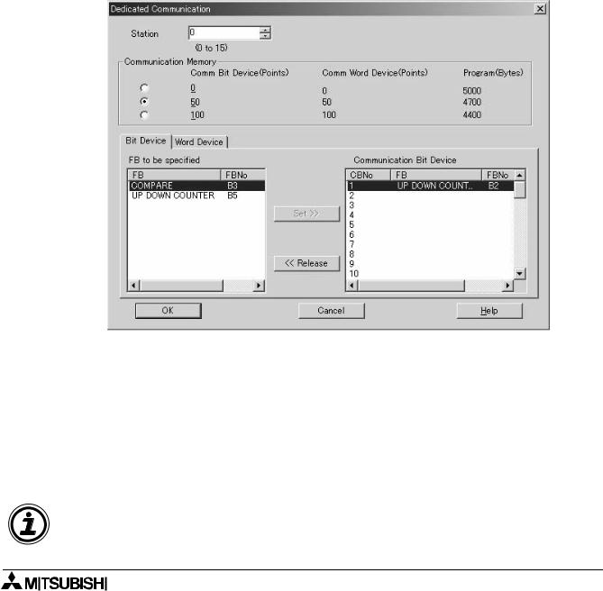
5 ) The Dedicated Communication dialog box will appear.
A)
B)
C)
D)
A) Station Number
Set the Station Number of the controller from 0 to 15. The default station is 0. Communication is possible to a single α2 Controller when sending messages via RS-232. A networked α2 may have a station number higher than 0.
Setting range: 0 - 15
6 - 3
α2 Simple Application Controllers |
AL-VLS/WIN-E Settings for Dedicated Protocol 6 |
B) Communication Memory
The Communication Memory option allocates a section of the user-program memory for Communication Bit Devices or Communication Word Devices.
Table 6.2: Communication Memory usage
|
|
|
|
|
|
Communication |
Communication Word |
Memory Usage (bytes) |
|
|
Bit Device |
Device |
|
|
|
|
|
||
|
|
|
|
|
|
0 |
0 |
0 |
|
|
|
|
|
|
|
50 |
50 |
300 |
|
|
|
|
|
|
|
100 |
100 |
600 |
|
|
|
|
|
|
|
|
|
|
|
A maximum of 100 Function Block Bit Devices and 100 Function Block Words can be accessed. Total memory available to the user is 5000bytes with a 200 function block limit.
C) Communication Function Block Bit Device
To Set a Communication Bit Device choose a number in the right hand “Communication Bit Device” block, then highlight the Function Block in the “FB to be Specified” box. Click on the “Set” button to match the Function Block to the data transmission address.
To release a Function Block, highlight the Function Block line in the right hand box and then press the “Release” button. The Communication Bit Device Number will be cleared.
The transmit data will show whether the Function Block output signal is On or Off. Function Blocks without outputs will not appear in the display.
Note:
No device can be chosen if the Communication Memory is specified as 0.
6 - 4

α2 Simple Application Controllers |
AL-VLS/WIN-E Settings for Dedicated Protocol 6 |
D) Communication Function Block Word Device
To set a Communication Word Device choose a number in the right hand “Communication Word Device” block, then highlight the Function Block in the “FB Word Output parameter to be specified” box. Click on the “Set” button to match the Function Block to the data transmission address.
To release a Communication Word Device, highlight the Parameter line in the right hand box and then press the “Release” button. The Communication Word Device will be cleared.
The transmit data will show the word value of the parameter chosen.
Function Block without Word parameters will not appear in the display.
Note:
No devices can be chosen if the Communication Memory is specified as 0.
After the parameters are entered, the program must be downloaded to the controller and the power cycled before the Dedicated Protocol can be used. Cycling the power saves the settings into the α2 internal EEPROM memory. Please cycle the power whenever the communication method (Not Use, Modem, GSM, Other) is changed.
6 - 5