

α2 Simple Application Controllers |
The Command String 7 |
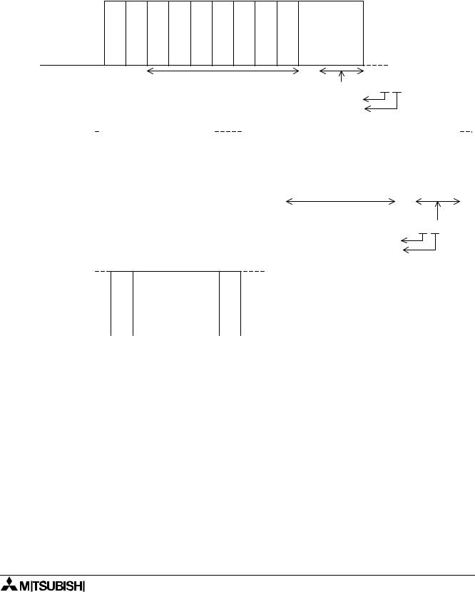
7.3.10Sum Check
The Sum Check is the four digit Hexadecimal total of the numbers between the Format No. and the ETX command. The Sum Check numbers are Hexadecimal numbers with the Low Byte written directly after the ETX command and the High Byte as the last two digits in the Command String. The Sum check is used to verify the validity of the message.
Format B - READ message
S
T
X
Computer
α2 Controller
No. comm bytes |
Format No. |
Station No. |
Command |
No. of devices Device code Device No. (LB) Device No. (HB) |
07H 41H 00H 00H 01H 42H 01H 00H
41H+00H+00H+01H+42H+01H+00H
X |
checkSum (LB) |
checkSum (HB) |
E |
|
|
T |
|
|
|
85H |
00H |
|
|
|
Sum Check = 00 85 H
Higher byte Lower byte
|
STX |
No. comm bytes |
Format No. |
Station No. |
Complete flag |
|
|
|
03H |
40H |
00H |
21H |
|
|
|
|
|
|
|
|
|
|
|
|
|
or |
|
|
|
STX |
|
No. comm bytes |
|
Format No. |
|
Station No. |
|
NAK |
|
|
|
|
|||||
|
|
04H |
|
|
|
|
|
|
STX |
No. comm bytes |
Format No. |
Station No. |
Command |
No. of devices |
Device status |
ETX |
Sum check (LB) |
Sum check (HB) |
|
05H |
41H |
00H |
00H |
01H |
00H |
|
42H |
00H |
|
|
|
|
|
|
|
|
|
|
41H+00H+00H+01H+00H
Sum C heck = 00 42 H
Higher byte
Lower byte
Error Code
7 - 13

α2 Simple Application Controllers |
The Command String 7 |
7.3.11Error Codes
If there is a problem in the communication line or in the command string, the α2 controller will return an error message. The error message will follow an NAK reply as shown below.
Table 7.10: Error Codes for Format “A” Transmissions
Code |
Error |
Error Description |
|
|
|
|
|
01H |
Sum Check error |
There is an error in the Sum Check value used in Protocol Format “B”. |
|
|
|
|
|
|
|
There is a discrepancy in the number of communication bytes in the |
|
02H |
Protocol error |
message. |
|
|
|||
|
|
Command for READ, WRITE or RUN/STOP operation is incorrect. |
|
|
|
|
|
|
|
The data stored in the device specification is outside the device |
|
|
|
range. |
|
03H |
Device error |
The Device Status setting value in out of the intended devices’s range |
|
|
|
||
|
|
The write protection for the memory cassette is enabled. |
|
|
|
|
|
04H |
Remote error |
There is a problem in the remote Start/Stop operation. Usually the |
|
cause of this error is an error in the controller program. |
|||
|
|
||
|
|
|
|
05H |
Date/Time error |
The Date or Time is invalid. |
|
|
|
|
|
|
|
|
7 - 14