

Литература / UMTS-Report
.pdfUMTS 30.06 version 3.0.0 |
41 |
TR 101 146 V3.0.0 (1997-12) |
2.5.4 Channel coding/interleaving for control channels
2.5.4.1 Dedicated Control Channel
The dedicated control channel (DCCH) uses the same rate 1/3 convolutional coding as the traffic channels. Intra-frame block interleaving is carried out after channel coding. Mapping to the Dedicated Physical Data Channel is done in exactly the same way as for dedicated traffic channels.
2.5.4.2 Downlink Common Control Channels
The downlink common control channels (BCCH, FACH, and PCH) use the same rate 1/3 convolutional coding as the traffic channels. Intra-frame block interleaving is carried out after channel coding before mapping to the Primary and Secondary Common Control Physical Channels.
In the case of the Secondary CCPCH, the FACH and PCH are time multiplexed on a frame-by-frame basis within the super-frame structure. The set of frames allocated to FACH and PCH respectively is broadcasted on the BCCH.
2.5.5 Example mapping for the test services
This section exemplifies the general channel coding and service multiplexing for some of the services used in the performance evaluation For simplicity, only the uplink mapping is shown.
2.5.5.1 8 kbps bearer
This bearer is used for the 8 kbps speech service. In this case, a 8 kbps speech frame appended with a 8 bits CRC is channel coded and mapped to a 32 kbps DPDCH according to Figure 13. Unequal repetition is used to match the 28.8 kbps data rate after channel coding to the closest DPDCH rate.
|
|
|
|
|
Data (80 bits) |
CRC (8) |
+ |
|
Tail (8) |
|
|
|
|
|
Conv. coding Rate 1/3, K=9 3*96 = 288 bits
Unequal repetition (9→10)
|
|
|
Þ 32 kbps DPDCH |
|
288*10/9 = 320 bits |
|
|
|
|
|
|
Figure 13 Channel coding and service mapping for an 8 kbps bearer (8 kbps speech service)
2.5.5.2 144 kbps bearer
This bearer is used for the 144 kbps LCD service. In this case, a 144 kbps data frame is RS coded, convolutional coded frame, and mapped to a 512 kbps DPDCH according to Figure 14. Code puncturing is used to match the 542.4 kbps data rate after channel coding to the closest DPDCH rate.
Data (1440 bits)
RS code Rate 180/225
|
|
|
|
|
|
|
Data (1800 bits) |
|
+ |
|
Tail (8) |
|
|
|
|
|
|
Conv. code Rate 1/3, K=9 3*1808 = 5424 bits
Code puncturing (339→320)
|
|
|
Þ 512 kbps DPDCH |
|
5424*320/339 = 5120 bits |
|
|
|
|
|
|
Figure 14 Channel coding and service mapping for a 144 kbps bearer (144 kbps LCD service)

UMTS 30.06 version 3.0.0 |
42 |
TR 101 146 V3.0.0 (1997-12) |
2.5.5.3 384 kbps bearer
This bearer is used for the 384 kbps LCD service. In this case, a 384 kbps data frame is RS coded, convolutional coded frame, and mapped to a 1024 kbps DPDCH according to Figure 15. Unequal repetition is used to match the 964.8 kbps data rate after channel coding to the closest DPDCH rate.
Data (3840 bits)
RS code Rate 192/240
|
|
|
|
|
|
|
Data (4800 bits) |
|
+ |
|
3*Tail (24) |
|
|
|
|
|
|
Conv. code Rate 1/2, K=9 2*4824 = 9648 bits
Unequal repetition (603→640)
|
|
|
Þ 1024 kbps DPDCH |
|
9648*640/603 = 10240 bits |
|
|
|
|
|
|
Figure 15 Channel coding and service mapping for a 384 kbps bearer (384 kbps LCD service)
2.5.5.4 480 kbps bearer
This bearer is used for the 384 kbps UDD service. In this case, 16 parallel blocks of 300 bits each are appended with a 12 bits header (CRC and Sequence Number). Each block is convolutionally encoded and mapped to a 1024 kbps DPDCH according to Figure 16. No rate matching is needed.
|
|
|
|
|
|
|
|
Data (300 bits) |
|
CRC+SN (12 bits) |
+ |
Tail (8) |
16 blocks per frame |
|
|
|
|
|
|
|
Conv. code Rate 1/2, K=9
|
|
|
Þ 1024 kbps DPDCH |
|
16*2*320 = 10240 bits |
|
|
|
|
|
|
Figure 16 Channel coding and service mapping for a 480 kbps bearer (384 kbps UDD service)
2.5.5.5 2.4 Mbps bearer
This bearer is used for the 2.048 Mbps UDD service. In this case, 80 parallel blocks of 300 bits each are appended with a 12 bits header (CRC and Sequence Number). Each block is convolutionally encoded and mapped to a 5 parallel 1024 kbps DPDCHs according to Figure 17. No rate matching is needed.
|
|
|
|
|
|
|
|
Data (300 bits) |
|
CRC+SN (12 bits) |
+ |
Tail (8) |
80 blocks per frame |
|
|
|
|
|
|
|
Conv. code Rate 1/2, K=9
|
|
|
Þ 5*1024 kbps DPDCH |
|
80*2*320 = 51200 bits |
|
|
|
|
|
|
Figure 17 Channel coding and service mapping for a 2.4 Mbps bearer (2.048 Mbps UDD)
UMTS 30.06 version 3.0.0 |
43 |
TR 101 146 V3.0.0 (1997-12) |
2.6 Radio Resource Functions
2.6.1 Random Access
2.6.1.1 Random-Access burst structure
The structure of the Random-Access burst is shown in Figure 18. The Random-Access burst consists of two parts, a preamble part of length 16*256 chips (1 ms) and a data part of variable length.
|
|
|
|
|
|
Preamble part |
|
Data part |
|
|
|
|
|
|
|
|
|
|
|
|
16*256 chips |
|
Variable length |
|
Figure 18 Structure of the Random-Access burst
2.6.1.1.1 Preamble part
Figure 19 shows the structure of the preamble part of the Random-Access burst.
Preamble
p0  p1 p2
p1 p2  p3 p4
p3 p4  p5 p6
p5 p6  p7 p8
p7 p8  p9 p10 p11 p12 p13 p14 p15
256 chips
p0, p1, ..., p15: Preamble sequence
Figure 19 Structure of Random-Access burst preamble part
The preamble consists of 16 symbols (the preamble sequence) spread by an Orthogonal Gold code (the preamble code) of length 256 chips.
The preamble sequence is randomly chosen from a set of 16 orthogonal code words of length 16. All 16 preamble sequences are available in each cell.
Neighbouring base stations use different preamble codes and information about what preamble code(s) are available in each cell is broadcasted on the BCCH.
2.6.1.1.2 Data part
Figure 20 shows the structure of the data part of the Random-Access burst. It consists of the following fields (the values in brackets are preliminary values):
∙Mobile station identification (MS ID) [16 bits]. The MS ID is chosen at random by the mobile station at the time of each Random-Access attempt.
∙Required Service [3 bits]. This field informs the base station what type of service is required (short packet transmission, dedicated-channel set-up, etc.)
∙An optional user packet. The possibility to append uplink user packets directly to the RandomAccess request is described in Section 2.7.1.
∙A CRC to detect errors in the data part of the Random-Access burst [8 bits].
MS ID Req. Ser. Optional user packet CRC
Figure 20 Structure of Random-Access burst data part
The spreading and modulation of the data part of the Random-Access burst is basically the same as for the uplink dedicated physical channels, see Figure 6. The scrambling code for the data part is chosen based on the base-station-specific preamble code, the randomly chosen preamble sequence, and the randomly chosen Random-Access time-offset, see 2.6.1.2. This guarantees that two simultaneous Random-Access attempts that use different preamble codes and/or different preamble sequences will not collide during the data part of the Random-Access bursts.

UMTS 30.06 version 3.0.0 |
44 |
TR 101 146 V3.0.0 (1997-12) |
2.6.1.2 Random-Access procedure
Before making a Random-Access attempt, the mobile station should do the following
∙Acquire chip and frame synchronisation to the target base station according to 2.6.4
∙Acquire information about what Random-Access (preamble) codes are available in the cell from the BCCH
∙Estimate the uplink path-loss from measurements of the received BS power and use this path-loss estimate, together with the uplink receieved interference level and received SIR target, to decide the transmit power of the Random-Access burst. The uplink interference level as well as the required received SIR are broadcasted on the BCCH.
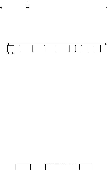
The mobile station then transmits the Random-Access burst with a n*2 ms time-offset (n=0..4) relative to the received frame boundary, see Figure 21. The value of n, i.e. the time-offset, is chosen at random at each Random-Access attempt.
Tf = 10 ms
|
|
2 ms |
|
|
|
|
|
|
|
|
|
|
PS #1 |
|
|
Data part |
|
|
|
|
|
|
|
|
|
|
|
|
|
|
PS #2 |
|
|
Data part |
|
|
|
|
|
|
|
PS #1 |
Data part |
|
|
Received frame boundary
PS: Preamble Sequence
Figure 21 Possible transmission timing for parallel Random-Access attempts
A typical implementation of the base-station random-access receiver for a given preamble code and preamble sequence is illustrated in Figure 22. The received signal is fed to a matched filter, matched to the preamble code. The output of the matched filter is then correlated with the preamble sequence. The output of the preamble correlator will have peaks corresponding to the timing of any received RandomAccess burst using the specific pramble code and preamble sequence. The estimated timing can then be used in a ordinary RAKE combiner for the reception of the data part of the Random-Access burst.
Preamble correlator |
|
|
Matched |
Peak |
Timing |
filter |
detector |
estimator |
Preamble |
Ts |
|
sequence |
|
|
|
|
RAKE |
Figure 22 Base-station Random-Access receiver.
With this scheme, a base station may receive up to 80 (16 preamble sequences and 5 time-offsets) Random-Access attempts within one 10 ms frame using only one (preamble) matched filter.
Upon reception of the Random-Access burst, the base station responds with an Access Grant message on the FACH. In case the Random Access request is for a dedicated channel (circuit-switched or packet) and the request is granted, the Access Grant message includes a pointer to the dedicated physical channel(s) to use. As soon as the mobile station has moved to the dedicated channel, closedloop power control is activated.
UMTS 30.06 version 3.0.0 |
45 |
TR 101 146 V3.0.0 (1997-12) |
2.6.2 Code allocation
2.6.2.1 Downlink
2.6.2.1.1 Channelization codes
The channelization code for the BCCH is a predefined code which is the same for all cells within the system.
The channelization code(s) used for the Secondary Common Control Physical Channel is broadcasted on the BCCH.
The channelization codes for the downlink dedicated physical channels are decided by the network. The mobile station is informed about what downlink channelization codes to receive in the downlink Access Grant message that is the base-station response to an uplink Random Access request. The set of channelization codes may be changed during the duration of a connection, typically as a result of a change of service or an inter-cell handover. A change of downlink channelization codes is negotiated over the DCCH.
2.6.2.1.2 Scrambling code
The downlink scrambling code is assigned to the cell (sector) at the initial deployment. The mobile station learns about the downlink scrambling code during the cell search process, see Section 2.6.4.
2.6.2.2 Uplink
2.6.2.2.1 Channelization codes
Each connection is allocated at least one uplink channelization code, to be used for the Dedicated Physical Control Channel. In most cases, at least one additional uplink channelization code is allocated for a Dedicated Physical Data Channel. Further uplink channelization codes may be allocated if more than one DPDCH are required.
As different mobile stations use different uplink scrambling codes, the uplink channelization codes may be allocated with no co-ordination between different connections. The uplink channelization codes are therefore always allocated in a predetermined order. The mobile-station and network only need to agree on the number of uplink channelization codes. The exact codes to be used are then implicitly given.
2.6.2.2.2 Primary scrambling code
The uplink primary scrambling code is decided by the network. The mobile station is informed about what primary scrambling code to use in the downlink Access Grant message that is the base-station response to an uplink Random Access Request.
The primary scrambling code may, in rare cases, be changed during the duration of a connection. A change of uplink primary scrambling code is negotiated over the DCCH.
2.6.2.2.3 Secondary (optional) scrambling code
The secondary uplink scrambling code is an optional code, typically used in cells without multiuser detection in the base station The mobile station is informed if a secondary scrambling code should be used in the Access Grant Message following a Random-Access request and in the handover message.
What secondary scrambling code to use is directly given by the primary scrambling code. No explicit allocation of the secondary scrambling code is thus needed.
2.6.3 Power control
2.6.3.1 Uplink power control
2.6.3.1.1 Closed loop power control
The uplink closed loop power control adjusts the mobile station transmit power in order to keep the received uplink Signal-to-Interference Ratio (SIR) at a given SIR target.
UMTS 30.06 version 3.0.0 |
46 |
TR 101 146 V3.0.0 (1997-12) |
The base station should estimate the received DPCCH power after RAKE combining of the connection to be power control. Simultaneously, the base station should estimate the total uplink received interference in the current frequency band. The base station then generates TPC commands according to the following rule:
SIRest > SIRtarget,UL → TPC command = “down”
SIRest < SIRtarget,UL → TPC command = “up”
Upon the reception of a TPC command, the mobile station should adjust the transmit power of both the
DPCCH and the DPDCH in the given direction with a step of TPC dB. The step size TPC is a parameter that may differ between different cells.
In case of soft handover, the mobile station should adjust the power with the largest step in the “down” direction ordered by the TPC commands received from each base station in the active set.
2.6.3.1.2 Outer loop (SIR target adjustment)
The outer loop adjusts the SIR target used by the closed-loop power control. The SIR target is independently adjusted for each connection based on the estimated quality of the connection. In addition, the power offset between the uplink DPDCH and DPCCH may be adjusted. How the quality estimate is derived differs for different service combinations. Typically a combination of estimated biterror rate and frame-error rate is used.
2.6.3.1.3 Open-loop power control
Open-loop power control is used to adjust the transmit power of the physical Random-Access channel. Before the transmission of a Random-Access frame, the mobile station should measure the received power of the downlink Primary Common Control Physical Channel over a sufficiently long time to remove any effect of the non-reciprocal multi-path fading. From the power estimate and knowledge of the Primary CCPCH transmit power (broadcasted on the BCCH) the downlink path-loss including shadow fading can be found. From this path loss estimate and knowledge of the uplink interference level and the required received SIR, the transmit power of the physical Random-Access channel can be determined. The uplink interference level as well as the required received SIR are broadcasted on the BCCH.
2.6.3.2 Downlink power control
2.6.3.2.1 Closed loop power control
The downlink closed loop power control adjusts the base station transmit power in order to keep the received downlink SIR at a given SIR target
The mobile station should estimate the received DPCCH power after RAKE combining of the connection to be power control. Simultaneously, the mobile station should estimate the total downlink received interference in the current frequency band. The mobile station then generates TPC commands according to the following rule:
SIRest > SIRtarget,DL → TPC command = “down”
SIRest < SIRtarget,DL → TPC command = “up”
Upon the reception of a TPC command, the base station should adjust the transmit power in the given direction with a step of TPC dB. The step size TPC is a parameter that may differ between different cells.
2.6.3.2.2 Outer loop (SIR target adjustment)
The outer loop adjusts the SIR target used by the closed-loop power control. The SIR target is independently adjusted for each connection based on the estimated quality of the connection. In addition, the power offset between the downlink DPDCH and DPCCH may be adjusted. How the quality estimate is derived differs for different service combinations. Typically a combination of estimated bit-error rate and frame-error rate is used.

UMTS 30.06 version 3.0.0 |
47 |
TR 101 146 V3.0.0 (1997-12) |
2.6.4 Initial cell search
During the initial cell search, the mobile station searches for the base station to which it has the lowest path loss. It then determines the downlink scrambling code and frame synchronisation of that base station. The initial cell search uses the synchronization channel (SCH) described in Section 2.4.2.3, the structure of which is repeated in Figure 23 below.
|
|
Tslot = 256 chips |
|
|
|
||
Primary SCH |
|
|
|
|
|
|
|
|
cp |
|
|
cp |
|
cp |
|
|
|
|
|
|
|
|
|
|
|
|
|
|
|
|
|
Secondary SCH |
|
d1×cs |
|
|
d2×cs |
|
d16×cs |
Tframe = 16*Tslot
cp: Primary Synchronization Code
cs: Secondary Synchronization Code (one of 16 codes) d1, d2, ..., d16: Secondary SCH modulation
Figure 23 Structure of synchronization channel (SCH)
This initial cell search is carried out in three steps:
2.6.4.1 Step 1: Slot synchronisation
During the first step of the initial cell search procedure the mobile station uses the primary SCH to acquire slot synchronisation to the strongest base station. This is done with a single matched filter (or any similar device) matched to the primary synchronisation code cp which is common to all base stations. The output of the matched filter will have peaks for each ray of each base station within range of the mobile station, see Figure 24. Detecting the position of the strongest peak gives the timing of the strongest base station modulo the slot length. For better reliability, the matched-filter output should be non-coherently accumulated over a number of slots.
Matched |
|
|
Slot-wise |
|
|
Find |
Timing modulo Tslot |
|
filter (cp) |
|
|
accumulation |
|
|
maximum |
|
|
|
|
|
|
|
|
|
|
|
Tslot
Two rays from BSi |
One ray from BSj |
Figure 24 Matched-filter search for primary synchronization code to slot synchronization (timing modulo the slot length)
2.6.4.2 Step 2: Frame synchronisation and code-group identification
During the second step of the initial cell search procedure, the mobile station uses the secondary SCH to find frame synchronisation and identify the code group of the base station found in the first step. This is done by correlating the received signal at the positions of the Secondary Synchronisation Code with all possible (16) Secondary Synchronisation Codes. Note that the position of the Secondary Synchronisation Code is known after the first step, due to the known time offset between the Primary and the Secondary Synchronisation Codes. Furthermore, the unmodulated primary SCH can be used as a phase reference in the demodulation of the modulated SCH.
The correlation with the 16 different Secondary Synchronization Codes gives 16 different demodulated sequences. To achieve frame synchronization, the 16 demodulated sequences should be correlated with the 16 different cyclic shifts of the Secondary SCH modulation sequence {d1, d2, ..., d16}, giving a total
UMTS 30.06 version 3.0.0 |
48 |
TR 101 146 V3.0.0 (1997-12) |
of 256 different correlation values. By identifying the code/shift pair that gives the maximum correlation value, the code group as well as the frame synchronization is determined.
2.6.4.3 Step 3: Scrambling-code identification
During the third and last step of the initial cell-search procedure, the mobile station determines the exact scrambling code used by the found base station. The scrambling code is identified through symbol-by-symbol correlation over the Primary CCPCH with all scrambling codes within the code group identified in the second step. Note that, from step 2, the frame boundary and consequently the start of the scrambling code is known. Correlation must be carried out symbol-wise, due to the unknow modulation of the primary CCPCH.
After the scrambling code has been identified, the Primary CCPCH can be detected, super-frame synchronisation can be acquired and the systemand cell specific BCCH information can be read.
2.6.5 Handover
2.6.5.1 Intra-frequency handover
2.6.5.1.1 Soft handover
When in active mode, the mobile station continuously searches for new base stations on the current carrier frequency. This cell search is carried out in basically the same way as the initial cell search described in Section 2.6.4. The main difference compared to the initial cell search is that an active mobile station has received a priority list from the network. This priority list describes in which order the downlink scrambling codes should be searched for and does thus significantly reduce the time and effort needed for the scrambling-code search (step 3) described in Section 2.6.4.3. Also the second step may be reduced if the priority list does only include scrambling codes belonging to a subset of the total set of code groups. The priority list is continuously updated to reflect the changing neighbourhood of a moving mobile station.
During the search, the mobile station monitors the received signal level broadcasted from neighbouring base stations, compares them to a set of thresholds, and reports them accordingly back to the base station. Based on this information the network orders the mobile station to add or remove base station links from its active set. The active set is defined as the set of base station from which the same user information is sent, simultaneously demodulated and coherently combined, i.e. the set of mobile terminals involved in the soft handover.
An example algorithm for reporting signal level and optimising the active set can be found in Tdoc SMG2 UMTS A16/97.
From the cell-search procedure, the mobile station knows the frame offset of the CCPCH of potential soft-handover candidates relative to that of the source base station(s) (the base stations currently within the active set). When a soft handover is to take place, this offset together with the frame offset between the DPDCH/DPCCH and the Primary CCPCH of the source base station, is used to calculate the required frame offset between the DPDCH/DPCCH and the Primary CCPCH of the destination base station (the base station to be added to the active set). This offset is chosen so that the frame offset between the DPDCH/DPCCH of the source and destination base stations at the mobile-station receiver is minimised. Note that the offset between the DPDCH/DPCCH and Primary CCPCH can only be adjusted in steps of one DPDCH/DPCCH symbol in order to preserve downlink orthogonality.
2.6.5.1.2 Softer handover
Softer handover is the special case of a soft handover between sectors/cells belonging to the same base station site. Conceptually, a softer handover is initiated and executed in the same way as an ordinary soft handover. The main differences are on the implementation level within the network. For softer handover, it is e.g. more feasible to do uplink maximum-ratio combining instead of selection combining as the combining is done on the BTS level rather than on the BSC level.
2.6.5.2 Inter-frequency handover
In WCDMA the vast majority of handovers are within one carrier frequency, i.e. intra-frequency handover. Inter-frequency handover may typically occur in the following situations:
UMTS 30.06 version 3.0.0 |
49 |
TR 101 146 V3.0.0 (1997-12) |
∙Handover between cells to which different number of carriers have been allocated, e.g. due to different capacity requirements (hot-spot scenarios).
∙Handover between cells of different overlapping orthogonal cell layers using different carrier frequencies
∙Handover between different operators/systems using different carrier frequencies including handover to GSM.
A key requirement for the support of seamless inter-frequency handover is the possibility for the mobile station to carry out cell search on a carrier frequency different from the current one, without affecting the ordinary data flow. WCDMA supports inter-frequency cell search in two different ways, a dualreceiver approach and a slotted-downlink-transmission approach.
2.6.5.2.1 Dual-receiver
For a mobile station with receiver diversity, there is a possibility for one of the receiver branches to temporarily be reallocated from diversity reception and instead carry out reception on a different carrier.
2.6.5.2.2 Slotted downlink transmission
With slotted downlink transmission, it is possible for a single-receiver mobile station to carry out measurements on other frequencies without affecting the ordinary data flow. The principle of slotted downlink transmission is illustrated in Figure 25. When in slotted mode, the information normally transmitted during a 10 ms frame is compressed in time, either by code puncturing or by reducing the spreading factor by a factor of 2. In this way, a time period of up to 5 ms is created during which the mobile-station receiver is idle and can be used for interfrequency measurements. Note that the idle slot is created without any loss of data as the number of information bits per frame is kept constant, while the processin gain is reduced by either reducing the spreading factor or increasing the coding rate. As illustrated in Figure 25, the instantaneous transmit power is increased in the slotted frame in order to keep the quality (BER, FER, etc.) unaffected by the reduced processing gain.
Tf
Idle period available for interfrequency measurements
Figure 25 Downlink slotted transmission
When in slotted mode, slotted frames should occur periodically, as illustrated in Figure 25. The rate of slotted frames is variable and depends on the environment and the measurement requirements. It is estimated that a rate of slotted frames of 10 Hz, i.e. having a slotted frame every 10o ms is more than sufficient for e.g. the HCS environment.
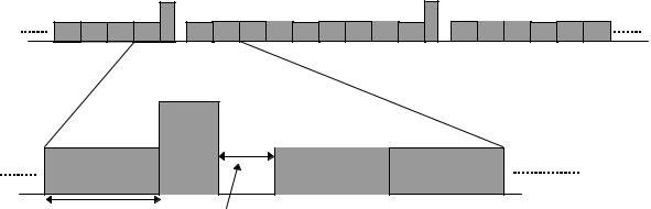
For services that allows for a larger delay, e.g. data services with interleaving over several frames, multiple frames can be compressed together in order to create a short measurement slot. This is useful e.g. for high-rate services where a reduction of the processing gain of e.g. a factor of two may be difficult. As an example, for a 2 Mbps service, with interleaving of 5 frames (50 ms), a 5 ms idle slot can be created by reducing the processing gain with only 10% during 5 frames, see Figure 26.

UMTS 30.06 version 3.0.0 |
50 |
|
|
|
|
TR 101 146 V3.0.0 (1997-12) |
|||||||
|
|
|
|
|
|
|
|
|
|
|
|
|
|
|
|
|
|
|
|
|
|
|
|
|
|
|
|
|
|
|
|
|
|
|
|
|
|
|
|
|
|
Compressed transmission during one interleaver span
Figure 26 Multi-frame compressed mode for long-delay services
2.6.5.2.3 Measurements from GSM with slotted mode
The WCDMA concept has shown that although the frame length is different from GSM frame length, the dual mode terminal can be implemented also with a single receiver chain similar to other UTRA solutions. The more important aspect than the frame length is the higher level frame structure which must be able to facilitate measurements from GSM system. The WCDMA multiframe structure of 120 ms is identical to GSM and thus similar measurements and GSM carrier decode procedures can be provided as in GSM. The principle is indicated in Figure 27, which shows the identical measurement time as for GSM. For the power measurements additional blank slots can be used during which it is estimated that 9 200 kHz GSM carriers could be measured for their power level when using a GSM like RF parts resulting to similar measurement performance as with GSM.
F-burst |
S-burst |
multi-frame |
|
GSM CCH frame |
frame |
||
|
GSM TCH/F
idle frame
WCDMA
blank slot
Figure 27. GSM measurement timing from WCDMA operation mode.