

Литература / UMTS-Report
.pdfUMTS 30.06 version 3.0.0 |
191 |
TR 101 146 V3.0.0 (1997-12) |
Table of Contents
1. OFDMA System Description....................................................................................................... |
193 |
|
2. OFDMA System Features........................................................................................................... |
194 |
|
3. OFDMA Logical Channels .......................................................................................................... |
195 |
|
3.1 |
Common Control Channels ................................................................................................. |
195 |
|
3.1.1 IACH (DL) ................................................................................................................. |
195 |
|
3.1.2 BCCH (DL)................................................................................................................ |
195 |
|
3.1.3 RACH ( Random Access Channel ) Physical Structure............................................ |
196 |
|
3.1.4 PCH(DL) ................................................................................................................... |
197 |
3.2 |
Dedicated Channels ............................................................................................................ |
197 |
4. OFDMA Resource Allocation/Physical Channel ......................................................................... |
198 |
|
4.1 |
Time and Frequency Parameters ........................................................................................ |
198 |
4.2 |
Multiple Access (Physical Channel Assignment)................................................................. |
199 |
4.3 |
Un-modulated Guard Carriers ............................................................................................. |
199 |
4.4 |
Antenna Diversity................................................................................................................. |
200 |
5. Radio Functions.......................................................................................................................... |
201 |
|
5.1 |
Channel Coding ................................................................................................................... |
201 |
|
5.1.1 Convolutional Encoding ............................................................................................ |
201 |
|
5.1.2 Reed Solomon Coding and Concatenated Coding ................................................... |
201 |
|
5.1.3 Turbo Coding ............................................................................................................ |
201 |
5.2 |
Interleaving .......................................................................................................................... |
201 |
5.3 |
Modulation and Demodulation Schemes............................................................................. |
201 |
|
5.3.1 Coherent Modulation................................................................................................. |
201 |
|
5.3.2 Differential Modulation .............................................................................................. |
202 |
5.4 |
Random Phase Shift Technique (RPS) ............................................................................... |
203 |
5.5 |
Random Orthogonal Transform (ROT)................................................................................ |
203 |
|
5.5.1 Transmitter Procedures ............................................................................................ |
204 |
|
5.5.2 Receiver Procedures ................................................................................................ |
204 |
5.6 |
Time and Frequency Synchronisation ................................................................................. |
204 |
|
5.6.1 Initial Modulation Timing Synchronisation (Downlink)............................................... |
205 |
|
5.6.2 Initial Modulation Timing Synchronisation (Uplink) ................................................... |
206 |
|
5.6.3 Modulation Timing Tracking (Uplink & Downlink) ..................................................... |
206 |
|
5.6.4 Initial Frequency Offset Synchronisation................................................................... |
207 |
|
5.6.5 Frequency Offset Tracking ....................................................................................... |
207 |
|
5.6.6 Synchronisation Accuracy......................................................................................... |
207 |
5.7 |
PA Linearity.......................................................................................................................... |
208 |
|
5.7.1 Interference to the Adjacent Band Signal ................................................................. |
208 |
|
5.7.2 Reduction of OFDM Peaks ....................................................................................... |
209 |
|
5.7.3 Real PA Nonlinearity Measurements ........................................................................ |
209 |
|
5.7.4 OFDMA receiver complexity (baseband) .................................................................. |
211 |
6. Radio Maintenance Control ........................................................................................................ |
212 |
|
6.1 |
Timing Advance ................................................................................................................... |
212 |
6.2 |
Handover ............................................................................................................................. |
212 |
|
6.2.1 Base Station Originated Hand Over.......................................................................... |
212 |
|
6.2.2 Mobile Assisted Hand Over (MAHO) ........................................................................ |
212 |
|
6.2.3 Forward Hand Over .................................................................................................. |
213 |
|
6.2.4 MSC Initiated Handover ............................................................................................ |
214 |
|
6.2.5 HCS and GSM handover .......................................................................................... |
214 |
6.3 |
Power Control ...................................................................................................................... |
215 |
7. Protocols..................................................................................................................................... |
216 |
|
7.1 |
Protocol Architecture ........................................................................................................... |
216 |
7.2 |
Random Frequency Hopping Operation .............................................................................. |
216 |
7.3 |
Dynamic Channel Allocation (Fast DCA)............................................................................. |
217 |
7.4 |
Dynamic Channel Allocation ( Simple DCA )....................................................................... |
219 |
8. System Deployment Aspects...................................................................................................... |
220 |
|
8.1 |
System Guard...................................................................................................................... |
220 |
8.2 |
Phased Deployment Model.................................................................................................. |
220 |
UMTS 30.06 version 3.0.0 |
192 |
TR 101 146 V3.0.0 (1997-12) |
8.3 Commonality Aspects.......................................................................................................... |
221 |
|
8.4 Deployment Options ............................................................................................................ |
221 |
|
8.5 Adaptive/Smart Antenna...................................................................................................... |
222 |
|
9. Simulation Description ................................................................................................................ |
223 |
|
9.1 Link Level Simulation Description (Differential Operation) .................................................. |
223 |
|
|
9.1.1 Speech Services ....................................................................................................... |
223 |
|
9.1.2 LCD Services ............................................................................................................ |
224 |
|
9.1.3 UDD Services ........................................................................................................... |
224 |
9.2 Link Level Simulation Description (Coherent Operation)..................................................... |
224 |
|
9.3 System Level Simulation Description (Differential Operation)............................................. |
224 |
|
|
9.3.1 Speech Services ....................................................................................................... |
224 |
|
9.3.2 LCD Services ............................................................................................................ |
224 |
|
9.3.3 UDD Services ........................................................................................................... |
224 |
10. Link Level Results (Differential Operation) ............................................................................... |
226 |
|
10.1 |
Speech............................................................................................................................... |
226 |
10.2 |
LCD 144 Simulation........................................................................................................... |
227 |
10.3 |
LCD 384 Simulation........................................................................................................... |
228 |
10.4 |
UDD 144, 384 Link Level Simulation ................................................................................. |
229 |
|
10.4.1 Mode A.................................................................................................................... |
229 |
|
10.4.2 Mode B.................................................................................................................... |
232 |
10.5 |
UDD 2048 Simulation ........................................................................................................ |
235 |
|
10.5.1 Mode B.................................................................................................................... |
235 |
11. Link Level Results (Coherent Operation).................................................................................. |
237 |
|
12. System Simulation Results (Differential Operation).................................................................. |
239 |
|
12.1 |
Simulation Conditions ........................................................................................................ |
239 |
|
12.1.1 Overview of System Level Simulation..................................................................... |
239 |
|
12.1.2 Statistical calculations............................................................................................. |
241 |
|
12.1.3 Pathloss calculation ................................................................................................ |
242 |
|
12.1.4 Fading calculation ................................................................................................... |
242 |
|
12.1.5 Neighbour BS Information....................................................................................... |
242 |
|
12.1.6 Interference Restriction........................................................................................... |
242 |
|
12.1.7 Traffic Management................................................................................................ |
243 |
|
12.1.8 MS Mobility.............................................................................................................. |
243 |
|
12.1.9 Handoff ................................................................................................................... |
243 |
|
12.1.10 Power Control ....................................................................................................... |
243 |
12.2 |
System Level Simulation Results (Speech)....................................................................... |
243 |
|
12.2.1 Outdoor to Indoor and Pedestrian A ....................................................................... |
244 |
|
12.2.2 Vehicular A.............................................................................................................. |
245 |
|
12.2.3 Indoor Office A ........................................................................................................ |
246 |
|
12.2.4 Speech System Level Simulation (Summary)......................................................... |
248 |
12.3 |
System Level Simulation Results (LCD 384)..................................................................... |
248 |
|
12.3.1 Vehicular A.............................................................................................................. |
248 |
12.4 |
System Level Simulation Results (UDD384) ..................................................................... |
251 |
|
12.4.1 Outdoor to Indoor and Pedestrian A ....................................................................... |
251 |
12.5 |
System Level Simulation Results (UDD2048) ................................................................... |
251 |
|
12.5.1 Indoor Office A ........................................................................................................ |
251 |
12.6 |
System Level Simulation Results (50%speech+50%UDD384) ......................................... |
252 |
|
12.6.1 Indoor Office A ........................................................................................................ |
252 |
13. Conclusion ................................................................................................................................ |
253 |
|
14. Annex........................................................................................................................................ |
254 |
|
15. Annex........................................................................................................................................ |
254 |
|
15.1 |
System Level Simulation Updates ..................................................................................... |
254 |
|
15.1.1 Vehicular A - LCD 384 ............................................................................................ |
254 |
|
15.1.2 Speech.................................................................................................................... |
254 |
|
15.1.3 UDD 384 - Pedestrian A ......................................................................................... |
255 |
15.2 |
Abbreviations ..................................................................................................................... |
258 |
15.3 |
References ........................................................................................................................ |
258 |
UMTS 30.06 version 3.0.0 |
193 |
TR 101 146 V3.0.0 (1997-12) |
1. OFDMA System Description
The most important aspects of the physical layer are the time/frequency structure and the OFDM parameters. The following table summarises the common parameters and key technical characteristics of the OFDMA air-interface.
Table 1: Physical Parameters
|
Parameter |
Value |
|
|
|
|
|
|
1 |
Sub-carrier spacing |
100[kHz]/24 = 4.1666[kHz] |
|
fSC [Hz] |
|
2 |
Effective modulation |
1/fsc = 240[µs] |
|
period TM[sec] |
|
3 |
Number of sub-carrier per |
24 sub-carriers ( 100[kHz] ) |
|
band slot |
|
4 |
Modulation period |
60[ms]/13/16 = 288.46[µs] |
|
|
( Half of GSM time slot ) |
5 |
Time slot length |
60[ms]/13/16 = 288.46[µs] |
|
TTS[sec] |
( Same as Modulation period ) |
6 |
Tx window shape |
Full cosine roll off ( Tukey ) |
7 |
Ramp period TR [sec] |
10[µs] |
8 |
Pre-Guard time |
38-a[µs] |
|
TG1[sec] |
|
9 |
Post-Guard time |
a[µs] |
|
TG2[sec] |
Proposal a=8.0µs |
10 |
Modulation unit |
Consists of 1 band slot and 1 time slot |
11 |
Modulation block |
4 time slots and 1 band slot |
UMTS 30.06 version 3.0.0 |
194 |
TR 101 146 V3.0.0 (1997-12) |
2. OFDMA System Features
The following summary shows some advantages of the OFDMA UTRA proposal.
∙Single core PHY layer minimizing hardware costs with 2 software driven MAC options
∙SFH TDMA based MAC for majority of UMTS services
∙TDD DCA MAC for unpaired spectrum allocations, asymmetrical services & unlicensed usage
∙Adaptive Modulation schemes for different channels
∙Robustness against multi-path and Doppler spread
∙Low computational overheads
∙Simple low cost low-bit rate only terminals feasible
∙Straightforward and efficient high bit rate support
∙Small guard band requirements ~ 100 kHz
∙High Spectral Efficiency achievable - 2 Mbits/s in 1.6 MHz feasible
∙No frequency planning option available - effective re-use factor of ~1
∙GSM Backwards Compatibility
∙Minimum Bandwidth Requirements for system deployment only 1.6 MHz (or less) and deployment possible in steps of 100kHz
∙Standard TDMA cellular planning and system enhancement techniques (smart antennas, hierarchical cell structures) can be supported
UMTS 30.06 version 3.0.0 |
195 |
TR 101 146 V3.0.0 (1997-12) |
3. OFDMA Logical Channels
OFDMA logical channel will follow the standards set in ITU and ETSI. In this section the logical channels for the OFDMA system are defined.
3.1 Common Control Channels
3.1.1 IACH (DL)
The IACH is the initial acquisition channel used for time and frequency synchronisation. In addition the IACH channel conveys information about the allocation of the BCCH channels. The IACH channel is a knowledge enclosed reference operation (KERO) burst (Figure 2) which includes 11 pilot symbols in order to ease detection. A KERO detector consists of a comb filter and correlator (Figure 3). IACH carries a 15 bit random sequence seed and can also be used for neighbour cell search for Mobile Assisted Hand Over (MAHO).
3.1.2 BCCH (DL)
The Broadcast Control Channel is a point-to-multipoint channel providing cell specific system information. The burst type of BCCH is a normal differential burst (Frequency Domain Differential Encoded). BCCH’s information is convolutionally encoded ( R = 1/3 ) and interleaved ( block interleaving ) over 64 BCCH bursts.
Allocation of IACH and BCCH bursts
Figure 1 shows IACH and BCCH allocation in the time and frequency domains. IACH bursts are allocated every 16 band slots ( fixed at every 1.6 MHz).
The IACH burst carries a 15 bit random sequence seed which is updated. This random sequence is split into three parts R1, R2 and R3 each consisting of 5 bits. R1 and R2 dictate which bandslot a BCCH burst will be allocated. The first BCCH burst after the IACH burst is allocated 3 timeslots later and R1 bandslots higher: The second BCCH burst is allocated 6 timeslots later and R2 bandslots higher. The third part of the random number, R3, dictates when the IACH burst will be transmitted. The next IACH burst is transmitted at 64 + R3 timeslots later on the same bandslot.
If system band is wider than 1.6[MHz] the same structure and contents of IACH and BCCH will be transmitted at 9 timeslots later on a 1.6[MHz] higher band. This ensures reception of the IACH and BCCH bursts.
All the base stations transmit IACH and BCCH bursts using the same scheme. The random numbers ( R1, R2, R3 ) are independent and therefore there is a low probability ( 3/16BS/64TS = 0.3[%] ) of collision.
No specific frequency channels are allocated for IACH and BCCH and therefore no management is required when using the same band in each cell. IACH and BCCH are also transmitted independently from the other channels (TCHs, etc.). When IACH and BCCH transmit at the same time and same bandslot as an active channel, the active channel is punctured.
MS actions
After the initial MS power on, the MS tunes to the bandslot which may transmit IACH channel (every 1.6[MHz] ) and sets KERO detector active. If no signal is received, it is concluded that the system is not operated in the frequency band or the location is out of service area.
If the system is operated, KERO detector will detect all IACHs transmitted by BSs which are located close to the MS.
MS select BS with the highest IACH signal , decodes 15 bits random seed in the IACH. Now the MS can tune to the BCCH.
Once IACH is detected, MS will not loose the position of future IACH and BCCH because the locations can be calculated uniquely by updating random number.

UMTS 30.06 version 3.0.0 |
|
|
196 |
TR 101 146 V3.0.0 (1997-12) |
|||
r e q u e n c y |
|
|
|
|
BCCH(k) |
|
|
F |
|
|
|
|
|
|
|
|
|
|
|
|
|
|
IACH and BCCH |
|
|
|
|
|
BCCH(k+1) |
|
Allocation |
|
|
|
|
|
|
|
|
|
|
|
9 TimeSlot |
|
|
9 TimeSlot |
|
|
|
|
|
IACH |
|
|
IACH |
16BandSlot |
6[MHz].(1) |
3 |
BandSlot |
|
|
|
|
|
BCCH(k) |
|
|
BCCH(k+3) |
|||
|
|
|
|
|
|
||
|
|
|
|
|
|
|
|
|
|
6 |
|
|
|
|
|
|
|
|
|
BCCH(k+1) |
|
|
|
|
|
|
(R1) |
BandSlot |
|
|
BCCH(k+2) |
|
|
IACH |
(64 + R3) |
TimeSlot |
IACH |
||
|
|
|
(R2) |
18.46[ms]+R3*288[us] |
|||
|
|
|
|
||||
|
|
|
|
|
|||
|
|
|
|
|
|
|
Time |
Figure 1: Location of IACH and BCCH channels
D Q P S K
Information
22 bits
Guard Carrier
P r e - d e t e r m i n e d
Pilot Symbols
Guard Carrier |
1 Band Slot |
|
(100[kHz]) |
K E R O :
KERO Burst Structure Knowled g e Enclosed
Reference Operation
Figure 2: KERO burst structure
120[us] |
Pilot |
delay |
Correlator |
Pilot carriers extraction
KERO detector
Figure 3: KERO detector
3.1.3 RACH ( Random Access Channel ) Physical Structure
The Random Access Channel is an uplink channel, carrying the information from the mobile station.
RACH burst
KERO burst (Figure 2) is also used for the RACH burst which can be detected by KERO

UMTS 30.06 version 3.0.0 |
197 |
TR 101 146 V3.0.0 (1997-12) |
detector in the BS. RACH carries a Random Access Number (RAN) which consists of 7 bits related to the Mobile Station Identification (MSID) number.
Allocation and Power Control of RACH
Two continuous time slots are prepared for the RACH burst, because propagation delay is unknown before communication starts between MS and BS. The RACH burst will be transmitted at the same power which was estimated as the down link signal strength (Open Loop Power Control) based on the received IACH and BCCH information.
MS and BS actions
MS measures RSSI and calculates adequate transmit power.
MS transmit RACH burst at calculated power and timing where a propagation delay of 0[µs] is assumed.
BS detects RACH using KERO detector and then decodes the RAN.
If detection and decoding was done successfully, BS reports back the RAN and time alignment value and location of DCCH (Dedicated Control Channel) through AGCH (Access Grant Channel) to the MS.
MS listens to AGCH, if the RAN corresponds to the RAN of the mobile, assignment of DCCH can be confirmed.
If the RAN is not detected, MS will transmit RACH again.
Frequency
Time Slots
for RACH
100[kHz] Band slot
288.46[us] |
|
|
|
|
Time |
Time slot |
|
|
|
|
|
|
|
|
|
|
|
|
|
RACH |
|
|
|
|
|
|
|
|
|
|
unknown |
RACH |
|
||
|
|
|
|||
|
propagation delay |
||||
|
|
Figure 4: RACH Structure |
|||
3.1.4 PCH(DL)
The Paging Channel is a downlink channel that is used to carry information to a mobile station. It can also be used for location update of mobile stations.
3.2 Dedicated Channels
DCCH (DL & UL)
The dedicated control channels are bi-directional and are used to carry control information toand from the mobile station to the network.
TCH (DL & UL)
The traffic channels are bi-directional or unidirectional channels which are used to carry the user information (Speech, data) between the network and mobile station.
AGCH
The Access Grant Channel reports TCCH allocations and timing advance information for specific MSs.

UMTS 30.06 version 3.0.0 |
198 |
TR 101 146 V3.0.0 (1997-12) |
4. OFDMA Resource Allocation/Physical Channel
4.1 Time and Frequency Parameters
The OFDMA air-interface utilises a time and frequency grid for basic physical channel structure.
Figure 5 shows the modulation blocks in the time and frequency grid. The resources (time and frequency) are allocated based on 

the type of services, operational environment/scenarios (i.e. give more flexibility). There are four mode of resource allocations:-
a) 1 x time slot + 1 x band slot |
n |
|
|
b) n x time slots + 1 x band slot |
i o |
1 Bandslot = |
|
od u l a t |
|||
100kHz |
|||
c) 1 x time slot + n x band slots |
|||
Unti |
|||
d) n x time slots + n x band slots |
M |
|
|
|
|
4.615ms frame |
|
|
|
4 frames (18.46ms) Interleave |
|
|
|
4 frames (18.46ms) Interleave |
1.1534ms sub-frame |
|
|
|
288.46[us] time slot |
|
Guard period |
Power control |
User Data |
Rx Burst |
|
|
Time Alignment |
|
|
|
Tx Burst |
|
Figure 6: Frame (TDMA) Structure
UMTS 30.06 version 3.0.0 |
199 |
TR 101 146 V3.0.0 (1997-12) |
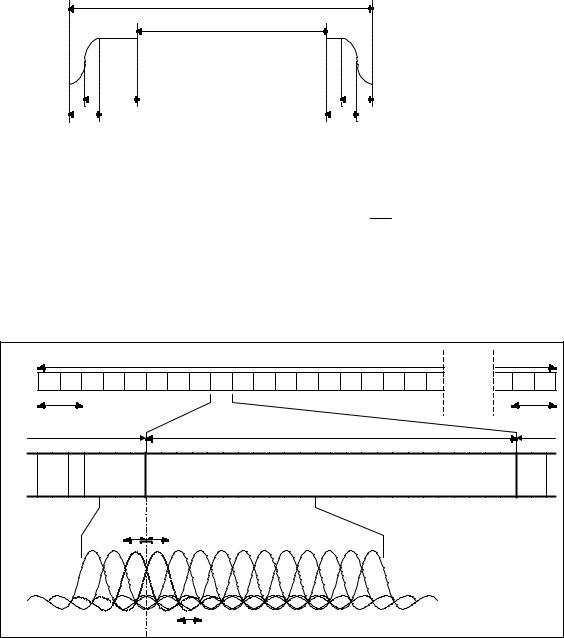
The Guard time is applied to be robust against very long multi-path delay. Tx windowing shape is full cosine roll off (Tukey window ), this reduces adjacent band emissions effectively.
Figure 7 shows the shape of the modulation unit.
Modulation Period (288.46µs)
Effective Modulation Period (240µs)
|
|
|
|
|
|
|
|
|
|
|
|
|
Ramp Time (10µs) |
|
|
|
|
|
Pre-Guard Time ( µs)... |
|
|
|
|
|
|
|
|
|
|
|
|
|
|
|
|
|
|
|
|
||
|
|
|
Ramp Time (10µs) |
|
|
|
|
|
Post-Guard Time ( µs)... |
||||
|
|
|
|
|
|
|
|||||||
Figure 7: OFDM Modulation Burst
The whole system frequency band is divided into small blocks (bandslots) with a fixed number of subcarriers. To maintain compatibility with GSM a bandslot of 100kHz is chosen which
consists of 24 subcarriers. Therefore the subcarrier spacing is 10024 [kHz] = 4.167[kHz] .
In each bandslot the two subcarriers at the edge of the bandslot are left unmodulated to relax receiver blocking requirements. In addition, the interference of two adjacent blocks of subcarriers is reduced, which may occur when their orthogonality is compromised due to nonlinear PA effects.
Adjacent bandslots can be concatenated to allow transmission of wideband services.
|
System Band |
Guard band |
Guard band |
Band Slot(100kHz) |
Band Slot(100kHz) |
(4.17kHz•24sub-carriers) |
(4.17kHz•24sub-carriers) |
Guard carrier |
Guard carrier |
(not used) |
(not used) |
|
OFDM sub-carrier spacing = 4.17kHz |
Figure 8: BDMA Frequency Structure
4.2 Multiple Access (Physical Channel Assignment)
The OFDMA utilises the time division multiple access with the aid of slow and fast dynamic channel allocation. Additionally frequency division multiple access (FDMA) is used with variable bandwidth.
4.3 Un-modulated Guard Carriers
In order to reduce adjacent channel emissions and facilitate easy bandslot separation one subcarrier at the edge of the bandslot is left unmodulated.

UMTS 30.06 version 3.0.0 |
200 |
TR 101 146 V3.0.0 (1997-12) |
Figure 9 depicts the scheme.
S 0 |
S 23 |
1 |
Bandslot Usage |
|
|
|
|
|
(2 unmodulated |
|
|
|
|
|
subcarriers) |
|
|
|
1 Bandslot = 100kHz |
2 |
Bandslot Usage |
|
|
|
|
|
|
||
S 0 |
|
|
(2 unmodulated |
S |
|
|
|
subcarriers) |
47 |
||
|
|
|
|
|
2 Bandslot = 200kHz
Figure 9 : Guard Carrier Allocation
4.4 Antenna Diversity
Receiver antenna diversity is utilised at the BS and the MS. Maximum ratio combining (MRC) is used to combine the two separate baseband signals after demodulation and is used with confidence weighting to form the received soft decision bits.