

Литература / UMTS-Report
.pdfUMTS 30.06 version 3.0.0 |
31 |
TR 101 146 V3.0.0 (1997-12) |
2.3 WCDMA Logical-Channel Structure
The WCDMA logical-channel structure basically follows the ITU recommendation ITU-R M.1035. The following logical-channel types are defined for WCDMA:
∙Common Control Channels
∙Broadcast Control Channel (BCCH)
∙Forward-Access Channel (FACH)
∙Paging Channel (PCH)
∙Random-Access Channel (RACH)
∙Dedicated Channels
∙Dedicated Control Channel (DCCH)
∙Dedicated Traffic Channel (DTCH)
These logical-channel types are described in more detail below.
2.3.1 Common Control Channels
2.3.1.1 BCCH - Broadcast Control Channel (DL)
The Broadcast Control Channel (BCCH) is a downlink point-to-multipoint channel that is used to broadcast systemand cell-specific information. The BCCH is mapped to the Primary Common Control Physical Channel (Primary CCPCH), see Section 2.4.2.1. The BCCH is always transmitted over the entire cell.
2.3.1.2 FACH - Forward Access Channel (DL)
The Forward Access Channel (FACH) is a downlink channel that is used to carry control information to a mobile station when the system knows the location cell of the mobile station. The FACH may also carry short user packets. The FACH is, together with the PCH, mapped to the Secondary Common Control Physical Channel (Secondary CCPCH), see Section 2.4.2.1. The FACH may be transmitted over only a part of the cell by using lobe-forming antennas.
2.3.1.3 PCH - Paging Channel (DL)
The Paging Channel (PCH) is a downlink channel that is used to carry control information to a mobile station when the system does not know the location cell of the mobile station. The PCH is, together with the FACH, mapped to the Secondary CCPCH. The PCH is always transmitted over the entire cell.
2.3.1.4 RACH - Random Access Channel (UL)
The Random Access Channel (RACH) is an uplink channel that is used to carry control information from a mobile station. The RACH may also carry short user packets. The RACH is mapped to the Physical Random Access Channel (PRACH), see Section 2.4.2.2. The RACH is always received from the entire cell.
2.3.2 Dedicated Channels
2.3.2.1 DCCH - Dedicated Control Channel (DL and UL)
The Dedicated Control Channel (DCCH) is a bidirectional channel that is used to carry control information between the network and a mobile station. The DCCH serves the same function as the two logical channels Stand-Alone Dedicated Control Channel (SDCCH) and Associated Control Channel (ACCH) defined within ITU-R M.1035. In WCDMA there is thus no distinction between dedicated control channels that are linked to a traffic channel and those that are not. The DCCH is, possibly together with one or several DTCHs, mapped to a Dedicated Physical Data Channel (DPDCH), see Section 2.4.1.1 and 2.4.1.2.

UMTS 30.06 version 3.0.0 |
32 |
TR 101 146 V3.0.0 (1997-12) |
2.3.2.2 DTCH - Dedicated Traffic Channel (DL and/or UL)
The Dedicated Traffic Channel (DTCH) is a bidirectional or unidirectional channel that is used to carry user information between the network and a mobile station. A DTCH is, together with a DCCH and possibly other DTCHs, mapped to a Dedicated Physical Data Channel (DPDCH).
2.3.3 Summary of logical-to-physical channel mapping
Figure 1 summarises the mapping of logical channels to physical channels. The physical channels are described in detail in Section 2.4.
Logical Channels |
Physical Channels |
BCCH |
Primary Common Control Physical Channel (Primary CCPCH) |
FACH |
Secondary Common Control Physical Channel (Secondary CCPCH) |
PCH |
|
RACH |
Physical Random Access Channel (PRACH) |
DCCH |
Dedicated Physical Data Channel (DPDCH) |
DTCH |
|
|
Figure 1 Logical-channel to physical-channel mapping |
UMTS 30.06 version 3.0.0 |
33 |
TR 101 146 V3.0.0 (1997-12) |
2.4 WCDMA Physical-Channel Structure
2.4.1 Dedicated physical channels
There are two types of dedicated physical channels, the Dedicated Physical Data Channel (DPDCH) and the Dedicated Physical Control Channel (DPCCH).
The DPDCH is used to carry dedicated data generated at layer 2 and above, i.e. the dedicated logical channels of Section 2.3.2.
The DPCCH is used to carry control information generated at layer 1. The control information consists of known pilot bits to support channel estimation for coherent detection, transmit power-control (TPC) commands, and (variable-length) rate information (RI). The rate information informs the receiver about the instantaneous rate of the different services multiplexed on the dedicated physical data channels.
2.4.1.1 Downlink dedicated physical channels
For the downlink, the DPDCH and the DPCCH are time multiplexed within each radio frame and transmitted with QPSK modulation.
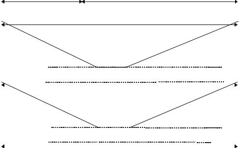
2.4.1.1.1 Frame structure
Figure 2 shows the principle frame structure of the downlink DPDCH/DPCCH. Each frame of length 10 ms is split into 16 slots, each of length Tslot = 0.625 ms, corresponding to one power-control period. Within each slot, the DPDCH and the DPCCH are time multiplexed. The slots of Figure 2 correspond to the power-control periods, see Section 2.6.3
DPCCH |
|
DPDCH |
|
|
|
|
|
Pilot |
TPC |
RI |
Data |
Npilot bits |
NTPC bits |
NRI bits |
Ndata bits |
0.625 ms, 20*2k bits (k=0..6)
|
|
|
|
|
|
|
|
|
|
|
Slot #1 |
Slot #2 |
|
Slot #i |
|
Slot #16 |
|||
|
|
|
|
|
|
|
|
|
|
|
|
|
|
|
|
|
|
|
|
Tf = 10 ms
|
|
|
|
|
|
|
|
|
|
|
Frame #1 |
Frame #2 |
|
Frame #i |
|
Frame #72 |
|||
|
|
|
|
|
|
|
|
|
|
|
|
|
|
|
|
|
|
|
|
Tsuper = 720 ms
Figure 2 Frame structure for downlink dedicated physical channels.
The parameter k in Figure 2 determines the total number of bits per DPDCH/DPCCH slot. It is related to the spreading factor SF of the physical channel as SF = 256/2k. The spreading factor may thus range from 256 down to 4.
The exact number of bits of the different fields in Figure 2 (Npilot, NTPC, NRI, and Ndata) is yet to be determined and is also expected to vary for different spreading factors and service combinations.
Note that connection-dedicated pilot bits are transmitted also for the downlink in order to support the use of downlink adaptive antennas. With downlink adaptive antennas, an omni-directional pilot channel will, in general, not propagate over the same radio channel as a dedicated physical channel transmitted in a narrow lobe.

UMTS 30.06 version 3.0.0 |
34 |
TR 101 146 V3.0.0 (1997-12) |
72 consecutive downlink frames constitute one WCDMA super frame of length 720 ms.
2.4.1.1.2 Spreading and modulation
Figure 3 illustrates the spreading and modulation for the DPDCH/DPCCH. Data modulation is QPSK where each pair of two bits are serial-to-parallel converted and mapped to the I and Q branch respectively. The I and Q branch are then spread to the chip rate with the same channelization code cch and subsequently scrambled by the same cell specific scrambling code cscramb.
|
cos(ωt) |
I |
p(t) |
|
DPDCH/DPCCH S→P |
cch cscramb |
sin( t) |
|
|
ω |
|
Q |
p(t) |
|
|
cch: channelization code cscramb: scrambling code
p(t): pulse-shaping filter (root raised cosine, roll-off 0.22)
Figure 3 Spreading/modulation for downlink dedicated physical channels
For multi-code transmission, each additional DPDCH/DPCCH should also be spread/modulated according to Figure 3. Each additional DPDCH/DPCCH should be assigned its own channelization code.
The channelization codes of Figure 3 are Orthogonal Variable Spreading Factor (OVSF) codes that preserve the orthogonality between downlink channels of different rates and spreading factors. The OVSF codes can be defined using the code tree of Figure 4.
c4,1 = (1,1,1,1)
c2,1 = (1,1)
c4,2 = (1,1,-1,-1)
c1,1 = (1)
c4,3 = (1,-1,1,-1)
c2,2 = (1,-1)
c4,4 = (1,-1,-1,1)
SF = 1 |
SF = 2 |
SF = 4 |
Figure 4 Code-tree for generation of Orthogonal Variable Spreading Factor (OVSF) codes
Each level in the code tree defines channelization codes of length SF, corresponding to a spreading factor of SF in Figure 3. All codes within the code tree cannot be used simultaneously within one cell. A code can be used in a cell if and only if no other code on the path from the specific code to the root of the tree or in the sub-tree below the specific code is used in the same cell. This means that the number of available channelization codes is not fixed but depends on the rate and spreading factor of each physical channel.
The downlink scrambling code cscramb is a 40960 chips (10 ms) segment of a length 218-1 Gold code repeated in each frame. The total number of available scrambling codes is 512, divided into 16 code groups with 32 codes in each group. The grouping of the downlink codes is done in order to facilitate a fast cell search, see Section 2.6.4.
The pulse-shaping filters are root raised cosine (RRC) with roll-off α=0.22 in the frequency domain.

UMTS 30.06 version 3.0.0 |
35 |
TR 101 146 V3.0.0 (1997-12) |
2.4.1.2 Uplink dedicated physical channels
For the uplink, the DPDCH and the DPCCH are IQ/code multiplexed within each radio frame and transmitted with dual-channel QPSK modulation. Each additional DPDCHs is code multiplexed on either the I- or the Q-branch with this first channel pair.
2.4.1.2.1 Frame structure
Figure 5 shows the principle frame structure of the uplink dedicated physical channels. Each frame of length 10 ms is split into 16 slots, each of length Tslot = 0.625 ms, corresponding to one power-control period. Within each slot, the DPDCH and the DPCCH are transmitted in parallel.
DPDCH |
Data |
|
Ndata bits |
||
|
DPCCH |
Pilot |
TPC |
RI |
|
Npilot bits |
NTPC bits |
NRI bits |
||
|
0.625 ms, 10*2k bits (k=0..6)
|
|
|
|
|
|
|
|
|
|
|
Slot #1 |
Slot #2 |
|
Slot #i |
|
Slot #16 |
|||
|
|
|
|
|
|
|
|
|
|
|
|
|
|
|
|
|
|
|
|
Tf = 10 ms
|
|
|
|
|
|
|
|
|
|
|
Frame #1 |
Frame #2 |
|
Frame #i |
|
Frame #72 |
|||
|
|
|
|
|
|
|
|
|
|
|
|
|
|
|
|
|
|
|
|
Tsuper = 720 ms
Figure 5 Frame structure for uplink dedicated physical channels
The parameter k in Figure 5 determines the number of bits per DPDCH or DPCCH slot. It is related to the spreading factor SF of the physical channel as SF = 256/2k. The spreading factor may thus range from 256 down to 4. Note that the DPDCH and DPCCH may be of different rates, i.e. have different spreading factors and thus different values of k.
As for the downlink, the exact number of bits of the different fields in Figure 5 (Npilot, NTPC, NRI, and Ndata) is yet to be determined and is once again expected to vary for different spreading factors and service combinations.
72 consecutive uplink frames constitute one WCDMA super frame of length 720 ms.

UMTS 30.06 version 3.0.0 |
36 |
TR 101 146 V3.0.0 (1997-12) |
2.4.1.2.2 Spreading and modulation
Figure 6 illustrates the spreading and modulation for the uplink dedicated physical channels. Data modulation is dual-channel QPSK, where the DPDCH and DPCCH are mapped to the I and Q branch respectively. The I and Q branch are then spread to the chip rate with two different channelization codes cD/cC and subsequently complex scrambled by a mobile-station specific primary scrambling code c’scramb. The scrambled signal may then optionally be further scrambled by a secondary scrambling code
c’’ scramb.
|
Channelization |
|
|
|
|
|
|
codes (OVSF) |
|
|
|
|
|
|
cD |
|
|
|
|
cos(ωt) |
|
I |
|
|
c” scramb |
Real |
|
DPDCH |
|
c’scramb |
(optional) |
p(t) |
||
|
|
|
||||
|
cC |
|
I+jQ |
|
|
sin(ωt) |
|
|
|
|
|
||
DPCCH |
Q |
j |
|
|
Imag |
p(t) |
|
|
|
|
|||
cD,cC: channelization codes |
|
|
|
|
|
|
c’scramb: primary scrambling code
c’’ scramb: secondary scrambling code (optional)
p(t): pulse-shaping filter (root raised cosine, roll-off 0.22)
Figure 6 Spreading/modulation for uplink dedicated physical channels
For multi-code transmission, each additional DPDCH may be transmitted on either the I or the Q branch. For each branch, each additional DPDCH should be assigned its own channelization code. DPDCHs on different branches may share a common channelization code.
The channelization codes of Figure 6 are the same type of OVSF codes as for the downlink, see Figure 4. For the uplink, the restrictions on the allocation of channelization codes given in 2.4.1.1 are only valid within one mobile station.
The primary scrambling code is a complex code c’scramb = cI+jcQ, where cI and cQ are two different codes from the extended Very Large Kasami set of length 256.
The secondary scrambling code is a 40960 chips (10 ms) segment of a length 241-1 Gold code.
The pulse-shaping filters are root-raised cosine (RRC) with roll-off α=0.22 in the frequency domain.
2.4.2 Common physical channels
2.4.2.1 Primary and Secondary Common Control Physical Channel (CCPCH)
The Primary and Secondary Common Control Physical Channels are fixed rate downlink physical channels used to carry the BCCH and FACH/PCH respectively.
Figure 7 shows the principle frame structure of the CCPCH. The frame structure differs from the downlink dedicated physical channel in that no TPC commands or rate information is transmitted. The only layer 1 control information is the pilot bits needed for coherent detection.

UMTS 30.06 version 3.0.0 |
37 |
TR 101 146 V3.0.0 (1997-12) |
Pilot |
Data |
Npilot bits |
Ndata bits |
0.625 ms, 20*2k bits
|
|
|
|
|
|
|
|
|
|
|
Slot #1 |
Slot #2 |
|
Slot #i |
|
Slot #16 |
|||
|
|
|
|
|
|
|
|
|
|
|
|
|
|
|
|
|
|
|
|
|
|
|
|
|
Tf = 10 ms |
|
|
|
|
|
Frame #1 |
Frame #2 |
|
Frame #i |
|
Frame #72 |
||
|
|
|
|
|
|
|
|
|
|
|
|
|
|
|
|
|
|
Tsuper = 720 ms
Figure 7 Frame structure for downlink Common Control Physical Channels
The CCPCH is modulated and spread in the same way as the Downlink Dedicated Physical Channels, see Figure 3.
In the case of the Secondary CCPCH, the FACH and PCH are time multiplexed on a frame-by-frame basis within the super-frame structure. The set of frames allocated to FACH and PCH respectively is broadcasted on the BCCH.
The main difference between a CCPCH and a downlink dedicated physical channel is that a CCPCH is not power controlled and is of constant rate. The main difference between the Primary and Secondary CCPCH is that the Primary CCPCH has a fixed predefined rate (32 kbps) while the Secondary CCPCH has a constant rate that may be different for different cells, depending on the capacity needed for FACH and PCH. Furthermore, a Primary CCPCH is continuously transmitted over the entire cell while a Secondary CCPCH is only transmitted when there is data available and may be transmitted in a narrow lobe in the same way as a dedicated physical channel (only valid for FACH frames).
2.4.2.2 Physical Random Access Channel
The Physical Random Access Channel is described in Section 2.6.1.
2.4.2.3 Synchronisation Channel
The Synchronisation Channel (SCH) is a downlink signal used for cell search, see Section 2.6.4.
The SCH consists of two sub channels, the Primary and Secondary SCH. Figure 8 illustrates the structure of the SCH:
|
|
Tslot = 2560 chips |
|
|
|
|
|
|
|
|
|
|
|
|
256 chips |
|
|||||
Primary SCH |
|
|
|
|
|
|
|
|
|
|
|
|
|
|
|
|
|
|
|
|
|
|
cp |
|
|
|
|
cp |
|
cp |
||
|
|
|
|
|
|
|
|
|
|
|
Secondary SCH |
|
d1×cs |
|
d2×cs |
d16×cs |
|||||
|
|
|
|
|
|
|
|
|
|
|
Tframe = 16*Tslot
cp: Primary Synchronization Code
cs: Secondary Synchronization Code (one of 16 codes) d1, d2, ..., d16: Secondary SCH modulation
Figure 8 Structure of Synchronisation Channel (SCH)

UMTS 30.06 version 3.0.0 |
38 |
TR 101 146 V3.0.0 (1997-12) |
The Primary SCH consists of an unmodulated orthogonal Gold code of length 256 chips, the Primary Synchronisation Code, transmitted once every slot. The Primary Synchronisation Code is the same for every base station in the system and is transmitted time-aligned with the slot boundary as illustrated in Figure 8.
The Secondary SCH consists of one modulated Orthogonal Gold code of length 256 chips, the Secondary Synchronisation Code, transmitted in parallel with the Primary Synchronization channel. The Secondary Synchronisation Code is chosen from a set of 16 different codes {c1,c2,...,c16} depending on to which of the 16 different code groups (see Section 2.4.1.1.2) the base station downlink scrambling code cscramb belongs.
The Secondary SCH is modulated with a binary sequence d1, d2, ..., d16 of length 16 bits which is repeated for each frame. The modulation sequence, which is the same for all base stations, has good cyclic autocorrelation properties.
The multiplexing of the SCH with the other downlink physical channels (DPDCH/DPCCH and CCPCH) is illustrated in Figure 9. The figure illustrates how the SCH is only transmitted intermittently (one codeword per slot) and also that the SCH is multiplexed after long code scrambling of the DPDCH/DPCCH and CCPCH. Consequently, the SCH is non-orthogonal to the other downlink physical channels.
Lower position during 256 chips per slot
0 |
|
|
|
|
1 |
|
Σ |
|
|
SCH |
cp |
|
|
|
0 |
|
|
|
|
di |
|
|
|
|
|
cs |
|
|
|
DPDCH/DPCCH |
cch,1 |
Σ |
Σ |
To IQ modulator |
|
|
|||
& CCPCH |
|
|
|
|
|
|
|
cscramb |
|
|
cch,N |
|
|
|
Figure 9 Multiplexing of SCH
The use of the SCH for cell search is described in detail in Section 2.6.4.

UMTS 30.06 version 3.0.0 |
39 |
TR 101 146 V3.0.0 (1997-12) |
2.5 Channel Coding and Service Multiplexing
2.5.1 Channel coding/interleaving for user services
As shown in Figure 10, WCDMA offers three basic service classes with respect to forward-error- correction (FEC) coding:
∙Standard-services with convolutional coding only
∙High-quality services with additional outer Reed-Solomon coding
∙Services with service-specific coding, i.e. services for which the WCDMA layer 1 does not apply any pre-specified channel coding.
BER=10-3 |
|
|
|
|
|
|
Inner coding |
|
|
Inner |
|
|
|
|
|
|
|
|
|
(conv.) |
|
|
interleaving |
BER=10-6 |
|
|
|
|
|
|
|
|
|
|
|
|
|
|
|
|
|
|
|
|
|
||
Outer coding |
|
|
Outer |
|
|
Inner coding |
|
|
Inner |
||
|
|
(RS) |
|
|
interleaving |
|
|
(conv.) |
|
|
interleaving |
|
|
|
|
|
|
|
|
|
|
|
|
Service-specific coding
Figure 10 Basic FEC coding for WCDMA
2.5.1.1 Inner coding/interleaving
The inner convolutional coding is of rate 1/3 except for the highest rates where a rate 1/2 code is used. The code polynomials are given in octal form in Table 2.
Rate |
Constraint |
Generator |
Generator |
Generator |
Free distance |
|
length |
polynomial 1 |
polynomial 2 |
polynomial 3 |
|
|
|
|
|
|
|
1/3 |
9 |
557 |
663 |
711 |
18 |
|
|
|
|
|
|
1/2 |
9 |
561 |
753 |
N/A |
12 |
|
|
|
|
|
|
Table 2 Parameters for convolutional coding. Generator polynomials in octal form.
After convolutional coding, block interleaving is applied. For low-delay services, intra-frame interleaving over one 10 ms frame is applied. For services that allow for more delay, inter-frame interleaving over up to 15 frames (150 ms) is possible.
2.5.1.2 Outer coding/interleaving
The current assumption for the outer RS coding is a rate 4/5 code over the 28-ary symbol alphabet.
After outer RS coding, symbol-wise inter-frame block interleaving is applied.
2.5.2 Service multiplexing
Multiple services belonging to the same connection are, in normal cases, time multiplexed. Time multiplexing may take place either before or after the inner or outer coding as illustrated in Figure 11.

|
UMTS 30.06 version 3.0.0 |
40 |
|
|
|
|
|
|
|
|
TR 101 146 V3.0.0 (1997-12) |
|||||||||||||||||||
|
{ |
|
|
|
|
|
|
|
|
|
|
|
|
|
|
|
|
|
|
|
|
|
|
|
|
|
|
|
|
|
|
|
|
|
Time |
|
|
|
|
Outer |
|
|
|
|
|
|
|
|
|
|
|
|
|
|
|
|
|
|
DPDCH #1 |
||
|
|
|
|
Mux |
|
|
|
|
coding/interl. |
|
|
|
|
|
Time |
|
|
|
|
|
|
|
|
|
|
|
|
|||
|
|
|
|
|
|
|
|
|
|
|
|
|
|
|
|
|
|
|
Inner |
|
|
|
|
|
|
|
|
|
||
|
|
|
|
|
|
|
|
|
|
|
|
|
|
|
Mux |
|
|
|
|
|
|
|
|
|
|
|
|
|
||
Parallel |
|
|
|
|
|
|
|
|
|
|
|
|
|
|
|
|
|
|
coding/interl. |
|
|
|
|
|
Time |
|
DPDCH #2 |
|||
|
|
|
|
|
|
|
|
|
|
|
|
|
|
|
|
|
|
|
|
|
|
|
|
|
||||||
|
|
|
|
|
|
|
|
|
|
|
|
|
|
|
|
|
|
|
|
|
|
|
|
|
|
|||||
|
|
|
|
|
|
|
|
|
|
|
|
|
|
|
|
|
|
|
|
|
|
|
|
|
|
|||||
services |
|
|
|
|
|
|
|
|
|
|
|
|
|
|
|
|
|
|
|
|
|
|
|
|
|
|
||||
|
|
|
|
|
|
|
|
|
|
|
|
|
|
|
|
|
|
|
|
|
|
|
|
|
|
|
|
|||
|
|
|
|
|
|
|
|
|
|
|
|
|
|
|
|
|
|
|
|
|
|
|
|
|
|
|||||
|
|
|
|
|
|
|
|
|
|
|
|
|
|
|
|
|
|
|
|
|
|
|
|
|
|
Mux |
|
DPDCH #N |
||
|
|
|
|
|
|
|
|
|
|
|
|
|
|
|
|
|
|
|
|
|
|
|||||||||
|
|
|
|
|
|
|
|
|
|
|
|
|
|
|
|
|
|
|
|
|
|
|
|
|
|
|
|
|||
|
|
|
|
|
|
|
|
|
|
|
|
|
|
|
|
|
|
|
|
|
|
|
|
|
|
|
|
|||
|
|
|
|
|
|
|
|
|
|
|
|
|
|
|
|
|
|
|
|
|
|
|
|
|
|
|
|
|||
|
|
|
|
|
|
|
|
|
|
|
|
|
|
|
|
|
|
|
|
|
|
|
|
|
|
|
|
|
|
|
Figure 11 Service multiplexing of WCDMA
After service multiplexing and channel coding, the multi-service data stream is mapped to one or, if the total rate exceeds the upper limit for single-code transmission, several DPDCHs.
A second alternative for service multiplexing is to treat parallel services completely separate with separate channel coding/interleaving and mapping to separate DPDCHs in a multi-code fashion, see Figure 12. With this alternative scheme, the power and consequently the quality of each service can be separately and independently controlled. The disadvantage is the need for multi-code transmission which will have an impact on mobile-station complexity.
|
{ |
|
|
|
|
|
|
DPDCH #1 |
|
|
|
|
|
Coding/ |
|
|
|
||
|
|
|
|
interleaving |
|
|
|
|
|
|
|
|
|
|
|
|
|
|
|
|
|
|
|
|
|
|
|
|
|
|
|
|
|
|
|
|
|||
|
|
|
|
Coding/ |
|
|
DPDCH #2 |
|
|
Parallel |
|
|
|
interleaving |
|
|
|
|
|
services |
|
|
|
|
|
DPDCH #N |
|||
|
|
|
|
|
|||||
|
|
|
|
|
|||||
|
|
|
|
Coding/ |
|
||||
|
|
|
|
interleaving |
|
|
|
|
|
|
|
|
|
|
|
|
|
|
|
Figure 12 Alternative service multiplexing
2.5.3 Rate matching
After channel coding and service multiplexing, the total bit rate is almost arbitrary. The rate matching matches this rate to the limited set of possible bit rates of a Dedicated Physical Data Channel. The rate matching is somewhat different for uplink and downlink. The rule of unequal repetition for rate maching is given in part II of this document.
2.5.3.1 Uplink
For the uplink, rate matching to the closest uplink DPDCH bit rate is always based on unequal repetition (a subset of the bits repeated) or code puncturing. In general, code puncturing is chosen for bit rates less than ≈20% above the closest lower DPDCH bit rate. For all other cases, unequal repetition is done to the closest higher DPDCH bit rate. The repetition/puncturing patterns follow a regular predefined rule, i.e. only the amount of repetition/puncturing needs to be agreed on. The correct repetition/puncturing pattern can then be directly derived at both the transmitter and receiver side.
2.5.3.2 Downlink
For the downlink, rate matching to the closest DPDCH bit rate, using either unequal repetition or code puncturing, is only done for the highest rate (after channel coding and service multiplexing) of a variable-rate connection and for fixed-rate connections. For lower rates of a variable-rate connection, the same repetition/puncturing pattern as for the highest rate is used and the remaining rate matching is based on discontinuous transmission where only a part of each slot is used for transmission. This approach is used in order to simplify the implementation of blind rate detection in the mobile station.