

Литература / UMTS-Report
.pdf
UMTS 30.06 version 3.0.0 |
342 |
TR 101 146 V3.0.0 (1997-12) |
Table 3-9 : The contents of the 1/16-slot Synchronisation burst.
Symbol number (SN) |
Length of field |
Contents of field |
|
|
|
0-2 |
3 |
Tail symbols |
|
|
|
3-305 |
303 |
Data symbols |
|
|
|
306-432 |
127 |
Training sequence |
|
|
|
433-735 |
303 |
Data symbols |
|
|
|
736-738 |
3 |
Tail symbols |
|
|
|
739-749 |
11 |
Guard period |
|
|
|
Training sequence for the 1/16-slot Synchronisation burst:
TS = ( 1 1 1 1 1 1 1 0 1 1 1 0 1 1 0 1 1 1 1 0 1 0 0 0 1 0 1 1 0 0 1 0 1 1 1 1 1 0 0 0 1 0 0 0 0 0 0 1 1 0 0 1 1 0 1 1 0 0 0 1 1 1 0 0 1 1 1 0 1 0 1 1 1 0 0 0 0 1 0 0 1 1 0 0 0 0 0 1 0 1 0 1 0 1 1 0 1 0 0 1 0 0 1 0 1 0 0 1 1 1 1 0 0 1 0 0 0 1 1 0 1 0 1 0 0 0 0 )
Tail |
Data |
Training |
Data |
Tail Guard |
||||
|
|
|
|
|
|
|
|
|
|
3 |
39 |
93 |
39 |
3 |
10.5 |
|
|
|
|
|
|
|
|
|
|
|
|
|
|
|
|
|
|
|
|
72 ms
Figure 3-14 The 1/64-slot Synchronisation burst
Table 3-10 : The contents of the 1/64-slot Synchronisation burst.
Symbol number (SN) |
Length of field |
Contents of field |
|
|
|
0-2 |
3 |
Tail symbols |
|
|
|
3-41 |
39 |
Data symbols |
|
|
|
42-134 |
93 |
Training sequence |
|
|
|
135-173 |
39 |
Data symbols |
|
|
|
174-176 |
3 |
Tail symbols |
|
|
|
177-186.5 |
10.5 |
Guard period |
|
|
|
Training sequence for the 1/64-slot Synchronisation burst:
TS = ( 0 0 1 0 1 0 0 1 0 1 1 1 1 1 0 1 0 1 0 1 0 0 0 0 1 0 1 1 0 1 1 1 1 0 0 1 1 1 0 0 1 0 1 0 1 1 0 0 1
1 0 0 0 0 0 1 1 0 1 1 0 1 0 1 1 1 0 1 0 0 0 1 1 0 0 1 0 0 0 1 0 0 0 0 0 0 1 0 0 1 0 0 1 )
The 1/64-burst Synchronisation burst consists of 25 information symbols, 10 parity symbols and 4 tail symbols. The 78 data symbols are obtained by a convolutional code of rate ½.
3.4.4 Access burst
The Access burst is used for initial random access and after/for handover. The modulation is BOQAM. Since timing advance is not known at initial random access and handover, a longer guard period is needed for the Access burst than for traffic bursts. The length of the guard period, tguard, limits the maximum radius, rmax, of the cell, which can be seen in the equation below.
rmax = |
c × t guard |
(3-2) |
|
2 |
|||
|
|
where c is the speed of light.

UMTS 30.06 version 3.0.0 |
343 |
TR 101 146 V3.0.0 (1997-12) |
In Table 3-11 one can find the maximum cell radius for the two bursts. As can be seen, the 1/16-slot Access burst, the guard of which is set to 625 symbols, can handle cells with radius up to 36 km, while the 1/64-slot Access burst, the guard of which is set to 98.5 symbols, can handle cells with 5 km radius.
Table 3-11 : Maximum cell radius for the two access bursts.
Slot type |
Slot length [ms] |
tguard [ms] |
rmax [ km] |
1/16 |
288 |
240 |
36 |
|
|
|
|
1/64 |
72 |
33 |
5 |
|
|
|
|
Figure 3-15 and Table 3-12 show the 1/16-slot Access burst and Figure 3-16 and Table 3-13 show the 1/64-slot Access burst.
Tail |
Training |
Data |
Tail |
Guard |
|||
|
|
|
|
|
|
|
|
|
3 |
63 |
56 |
3 |
|
625 |
|
|
|
|
|
|
|
|
|
|
|
|
|
|
|
|
|
288 μs
Figure 3-15 The 1/16-slot Access burst.
Table 3-12 : The contents of the 1/16-slot Access burst.
Symbol number (SN) |
Length of field |
Contents of field |
|
|
|
0-2 |
3 |
Tail symbols |
|
|
|
3-65 |
63 |
Training sequence |
|
|
|
66-121 |
56 |
Data symbols |
|
|
|
122-124 |
3 |
Tail symbols |
|
|
|
125-749 |
625 |
Guard symbols |
|
|
|
Training sequence for the 1/16-slot Access burst:
TS = ( 1 1 1 1 1 0 0 0 0 0 1 0 0 0 0 1 1 0 0 0 1 0 1 0 0 1 1 1 1 0 1 0 0 0 1 1 1 0 0 1 0 0 1 0 1 1 0 1 1
1 0 1 1 0 0 1 1 0 1 0 1 0 1 )
The 1/16-burst Access burst consists of 18 information symbols, 6 parity symbols and 4 tail symbols. The 56 data symbols are obtained by a convolutional code of rate ½.
Tail |
Training |
Data |
Tail |
Guard |
||||
|
|
|
|
|
|
|
|
|
|
3 |
41 |
|
56 |
3 |
|
84.5 |
|
|
|
|
|
|
|
|
|
|
|
|
|
|
|
|
|
|
|
72 μs
Figure 3-16 The 1/64-slot Access burst.
Table 3-13 : The contents of the 1/64-slot Access burst
Symbol number (SN) |
Length of field |
Contents of field |
|
|
|
0-2 |
3 |
Tail symbols |
|
|
|
9-43 |
41 |
Training sequence |
|
|
|
44-99 |
56 |
Data symbols |
|
|
|
100-102 |
3 |
Tail symbols |
|
|
|
103-186.5 |
84.5 |
Guard symbols |
|
|
|
UMTS 30.06 version 3.0.0 |
344 |
TR 101 146 V3.0.0 (1997-12) |
The training sequence for the 1/64-slot Access burst is:
TS = ( 0 1 0 0 1 0 1 1 0 1 1 1 1 1 1 1 1 0 0 1 1 0 0 1 1 0 1 0 1 0 1 0 0 0 1 1 1 1 0 0 0 )
The 1/64-slot Access burst consists of 18 information symbols, 6 parity symbols and 4 tail symbols. The 56 data symbols are obtained by a convolutional code of rate ½.
3.4.5 Training Adaptation
It is desirable to be able to adapt the duration of the training sequence to transmission conditions. For example, longer training sequences may be needed for channels with large delay spreads, or for low C/I. This can be done within the definition of the Flexible Burst in Chapter 3.4.1.4. Also the Flexible Burst allows the frequency of training sequences can be altered to optimise the trade-off between training overhead and throughput, by allowing more frequent channel measurements for environments with fast moving terminals and less frequent measurements for slow moving mobiles.
The set of defined uplink and downlink transmission bursts could also be extended. To avoid additional overhead from longer training sequences, bursts intended for low bit rate bearers could be designed specifically for use in alternate frames (or even less frequently). As an example, a 1/32 slot burst could be used every other frame instead of a 1/64 slot every frame.
Training adaptation can be supported as part of link adaptation and also needs appropriate channel measurements, for example of channel quality and delay spread.
3.5 Modulation
The basic modulation parameters including pulse shaping are summarised in Table 3-14.
|
Table 3-14 : Basic modulation parameters |
|
|
|
|
Carrier symbol rate |
|
2.6 MSymbol/s |
|
|
|
Carrier spacing |
|
1.6 MHz |
|
|
|
Data modulation |
|
Binary Offset QAM |
|
|
Quaternary Offset QAM |
|
|
|
Pulse shaping |
|
Root Raised Cosine |
|
|
(roll-off 0.35) |
|
|
|
3.5.1 Data modulation
In this section, symbol rates and durations are defined, the mapping of bits onto signal point constellation is shown and the pulse shaping is defined.
3.5.1.1 Symbol rate
The symbol rate and symbol duration are shown in Table 3-15.
Table 3-15 : Summary of symbol rates and durations
|
Symbol rate |
Symbol duration |
|
|
|
WB-TDMA |
2.6 Msymbol/s |
0.384 μs |
|
|
|
3.5.1.2 Mapping of bits onto signal point constellation
In WB-TDMA the data modulation is either Binary Offset QAM (BOQAM), which is sometimes also referred to as Offset QPSK (OQPSK), or Quaternary Offset QAM (QOQAM), which is sometimes also referred to as Offset 16QAM.
Offset QAM may in general be expressed as:
UMTS 30.06 version 3.0.0 |
345 |
TR 101 146 V3.0.0 (1997-12) |
s(t) = êéåa2 k h(t - 2kT )úù cos(ω c t) - êéåa2k +1h(t - (2k + 1)T)úùsin(ω c t) , |
(3-3) |
|||
ë k |
û |
ë k |
û |
|
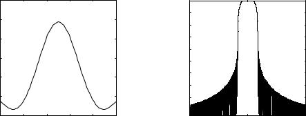
where wc=2pfc, fc is the carrier frequency, 1/T is the symbol rate (T=Tb for Binary Offset QAM and T=2Tb for Quaternary Offset QAM), ak is the kth data symbol taking on values of ±1 for Binary Offset QAM and ±1 and ±3 for Quaternary Offset QAM and h(t) is the impulse response of the shaping filter. The difference between Offset QAM and conventional QAM is the delay of T (half a symbol period for QAM) in the quadrature branch. This time shift prevents zero-crossing signal transitions, as shown in Figure 3-17 and Figure 3-18. This improves the Peak-to-Average Power Ratio, which makes Offset QAM more suitable for using with non-linear amplifiers.
The complex envelope of an Offset QAM signal is
u(t) = å[a2 k h(t − 2kT ) + j a2 k +1h(t − (2k + 1)T )]
k |
|
(3-4) |
|||
= å j (k mod 2 ) ak h(t − kT ) |
|
||||
|
|
|
|||
k |
|
|
|
||
1.5 |
|
|
|
|
|
|
|
|
|
||
1 |
|
|
O |
O |
|
0.5 |
|
|
|
|
|
0 |
|
|
|
|
|
-0.5 |
|
|
|
|
|
-1 |
|
|
O |
O |
|
-1.5 |
|
|
|
|
|
|
|
|
|
|
|
-1.5 |
-1 -0.5 0 |
0.5 1 1.5 |
|
||
Figure 3-17 Signal point constellation for BOQAM with rectangular pulse shaping (O, _______) and GMSK (----).
1 |
O |
|
O |
O |
O |
0.5 |
|
|
|
|
|
|
O |
|
O |
O |
O |
0 |
|
|
|
|
|
|
O |
|
O |
O |
O |
-0.5 |
|
|
|
|
|
-1 |
O |
|
O |
O |
O |
|
-1 |
-0.5 |
0 |
0.5 |
1 |
Figure 3-18 Signal point constellation for QOQAM with rectangular pulse shaping (O, ________)
3.5.1.3 Pulse shape filtering
In WB-TDMA, the pulse shaping filter has square root raised cosine spectrum with impulse response given by:
h(t) = |
E |
1 |
ésin π(1 - α)t / 2T + 4α t / 2T cosπ(1 |
+ α )t / 2T ù |
, |
(3-3) |
|||
|
|
ê |
|
|
|
||||
2T π t / 2T |
1 - (4α t / 2T)2 |
ú |
|||||||
|
|
|
|||||||
|
|
|
ê |
|
ú |
|
|
||
|
|
|
ë |
|
û |
|
|
||
which is uniquely defined by the roll-off factor a. Here, the value 0.35 is chosen for the roll-off factor a. E is the energy of the pulse h(t) (usually normalised to 1). The impulse response h(t) and the energy density spectrum of h(t) with the roll-off factor a=0.35 are depicted in Figure 3-19.
UMTS 30.06 version 3.0.0 |
347 |
TR 101 146 V3.0.0 (1997-12) |
3.6.2 Service mappings with WB-TDMA bursts
Table 3-17 : Examples of service mappings for WB-TDMA
Required |
Code |
Slot type |
Burst type |
Modulation |
Number of |
user bit |
rate |
|
|
|
basic physical |
rate |
|
|
|
|
channels per |
(kbits/s) |
|
|
|
|
frame |
|
|
|
|
|
|
|
|
|
|
|
|
|
|
|
|
|
|
8 |
0.5 |
1/64 |
Speech 2 |
BOQAM |
0.5 |
|
|
|
|
|
|
64 |
0.5 |
1/64 |
Speech 2 |
BOQAM |
4 |
|
|
|
|
|
|
144 |
0.5 |
1/16 |
Data |
BOQAM |
2 |
|
|
|
|
|
|
384 |
0.5 |
1/16 |
Data |
BOQAM |
5 |
|
|
|
|
|
|
1024 |
0.5 |
1/16 |
Data |
BOQAM |
14 |
|
|
|
|
|
|
2048 |
0.5 |
1/16 |
Data |
QOQAM |
14 |
|
|
|
|
|
|
|
|
|
|
|
|
3.6.3 Multirate concept with flexible bursts
The bit rate requirements for different applications could be met by using different modulation and coding schemes, as well as by allocation of a variable number of transmission slots. In the Adaptive Modulation concept the selection of the modulation and coding scheme is determined by the C/I at the mobile and the bit rate varied by adapting the slot duration.
As an example, the payload requirements for an 8kbps speech codec would vary from 40 symbols per frame (with Q-OQAM and 1/2 rate coding) to 120 symbols per frame (with B-OQAM and 1/3 rate coding). This assumes that 200 frames per second are used out of the available 216.68 frames per second (as in GSM). Therefore, using the Flexible Burst, and assuming training sequences of 27 symbols and 49 symbols respectively, the corresponding range of burst durations would be from 84 symbols to 186 symbols. The latter figure is almost the same as for the speech bursts.
Speech is considered to be a discontinuous data source, with a typical occupancy of 50%. Therefore efficient use of transmission capacity is achieved by multiplexing a number of such traffic channels into a Multiplexed Burst.
UMTS 30.06 version 3.0.0 |
348 |
TR 101 146 V3.0.0 (1997-12) |
4. Layer 2 Radio Protocols
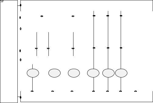
The following Figure 4-1 represents the layer structure and the protocols and algorithms of the WBTDMA radio interface. Algorithms are represented in dashed boxes.
LAYER 3 |
Core Network dependent Protocols |
|
|
|
|
|
Interworking Unit |
|
||
|
|
|
|
|
Admission Control |
|
|
|
Inter-Cell Handover |
Radio Bearer |
|
Radio Resource |
||
Algorithm |
|
Algorithm |
||
Control |
|
Control |
||
|
|
|
||
|
|
|
|
|
|
|
|
|
|
Logical Link Control
LAYER 2
|
Radio Link Control |
|
Link Adaptation |
|
|
|
|
Algorithm |
|
|
|
|
|
|
|
|
|
|
|
|
MUX |
|
Medium Access Control |
Resource Allocation |
|
|
|
|
Algorithm |
|
|
|
|
|
|
|
|
|
|
LAYER 1
Figure 4-1. WB-TDMA Radio interface
4.1 Overview of layer 2
The overall function of layer 2 is to realise radio bearers for layer 3 with respect to their QoS objectives. The first radio bearer, called the initial radio bearer, is mainly used to transport radio network layer (RNL) signalling, plus possibly messages destined to core network dependent control protocols. Other radio bearers are used to transport user data and network signalling. The initial radio bearer shall be maintained as long as other radio bearers have data to transfer. It is the last one to be released.
The set-up procedure for the initial radio bearer is triggered by layer 3 either after the reception of a paging message or because the MS wants to establish a connection to the fixed part of the core network. The set-up request is sent on a common uplink channel. The network allocates, in return, a MAC level identity to the MS. The procedure deals with collision and layer 3 solves contention between mobiles in order to guarantee that the MAC level identity is allocated to one and only one mobile. The MAC level identity is kept as long as the initial radio bearer is maintained. It is valid inside a given cell and has to be exchanged at each intercell handover.
The messages used to establish other radio bearers are layer 3 messages that are transported on the initial radio bearer.
Layer 2 is structured into two sub-layers (Figure 4-2) : the Logical Link Control (LLC) and the Radio Link Control / Medium Access Control (RLC/MAC) sub-layers. Service access points (SAP) are marked with dark dots. The RLC/MAC sub-layer has an internal structure. Therefore layer 2 is in fact composed of three types of protocol entities :
The LLC and RLC entities are created in association with a radio bearer and their function is to guarantee the negotiated QoS for the radio bearer.
UMTS 30.06 version 3.0.0 |
350 |
TR 101 146 V3.0.0 (1997-12) |
4.3.1 RLC
4.3.1.1 Functions of RLC
Two RLC entities (one in the MS and one in the network) are created by the management plane at each establishment of a radio bearer. These entities handle the service data units (SDU) coming from the LLC entities associated with the bearer. Their operating parameters are selected as a function of the QoS to be provided. A first task of RLC entities is to segment the SDU coming from LLC. A second task is to meet the QoS objectives that were assigned to them. For this purpose, they have elaborate control mechanisms at their disposal in order to deal with radio link quality fluctuations.
4.3.1.2 RLC Protocol
RLC entities are located both in mobile stations and in the network. The current working assumption is that the network RLCs are located in the base station. It has two operating modes, the first one to cater for real time (RT) transmissions and the second one to cater for non real time (NRT) transmissions. The RT mode uses power control and link adaptation mechanisms. The NRT mode uses power control and retransmission procedures (link adaptation for NRT services is realised with type-II hybrid ARQ, i.e. retransmission).
In the RT mode, the source RLC entity :
∙Uses for the bearer a set of transmission formats (channel coding, interleaving, modulation) agreed at bearer set-up by layer 3.
∙Has a dynamic set of traffic channels (TCH). This set can be reduced or increased through a request of the link adaptation algorithm to the local MAC entity (residing on the same side of the radio interface). Request may be done because e.g. there are traffic variations.
∙Is in charge of splitting the LLC flow between the set of traffic channels (TCH). The transmission format is selected separately for each TCH. RLC segments the LLC data into RLC-protocol data units (PDU) in accordance with the chosen transmission format, optionally computes a CRC, and then delivers the PDU to the physical layer for transmission.
∙In the RT mode, the sink RLC entity :
∙Has a dynamic set of traffic channels (TCH) (the same as the one of the source RLC). This set can be reduced or increased through a request of the link adaptation algorithm to the local MAC entity. Request may be done because e.g. there are radio condition variations.
∙Checks the CRC, if there is one, and discards the PDU if it is corrupted. Depending on the type of radio bearer the RLC entity is associated to, a corrupted PDU is either discarded or passed to LLC with a bad CRC indication.
∙Assembles received PDUs and delivers the resulting SDU to LLC.
In the NRT mode, the source RLC :
∙Uses the transmission format agreed at bearer set-up by layer 3.
∙Indicates to local MAC the data amount which is to be transmitted. The peer RLCs deduce from the data amount and the agreed transmission format the adapted segmentation.
∙Delivers PDUs to layer 1 when authorised by MAC, i.e. when resources are allocated to the radio bearer by the network.
∙In the NRT mode, the sink RLC :
∙Checks the CRC and alerts MAC when a PDU is received corrupted. It shall be noted that the role of RLC in the retransmission procedure is very limited. It only checks the CRC. All the signalling is handled by MAC entities.
∙Assembles the correct PDUs and delivers SDU to LLC.