

Литература / UMTS-Report
.pdf
UMTS 30.06 version 3.0.0 |
222 |
TR 101 146 V3.0.0 (1997-12) |
operators who wish to re-farm existing frequency allocations to this technology.
8.5 Adaptive/Smart Antenna
Adaptive antennas reduce the amount of co-channel interference, enabling operators to employ tighter frequency re-use thus increasing the network capacity. Conservative estimates suggest that an existing system designed with a frequency re-use plan of 4/3 could have its frequency plan tightened to 1/3 giving a potential factor of two improvement in capacity.
Interference reduction is achieved by using the principle of spatial filtering. Complex algorithms are used to adapt the antenna radiation pattern in order to maximise the signal-to- interference-and-noise (SINR) ratio and doing so "nulls" are created in the direction of interfering signals. This adaptation is performed on a per timeslot (or bandslot) basis (see figure below). The base station is able to constructively combine the multipath signals from the wanted mobile while "nulling out" those signals originating from interfering mobiles.
|
|
Mobile 1 |
|
|
Direct Ray |
|
Mobile 1 |
|
|
Mobile 2 |
Reflected Rays |
|
|
|
|
|
Interferer |
Interferer |
|
Mobile 2 |
|
Adaptively Synthesise |
|
|
Optimum Receive Weights |
|
|
for Each Mobile |
|
UMTS 30.06 version 3.0.0 |
223 |
TR 101 146 V3.0.0 (1997-12) |
9. Simulation Description
Performance evaluation of the OFDMA concept group has been carried out by simulation according to ETR-0402. The following simulation scenarios were considered during the first phase of simulations.
The two operational styles of the OFMDA proposal (using SFH and differential detection or coherent reception in combination with DCA) have been analysed.
For the first operation style (differential reception and SFH) the following scenarios were simulated.
Environment |
Propagation |
Service |
Cell Type |
Link Level |
System |
|
Model |
Mixture |
|
|
Level |
Vehicular |
Vehicular A |
UDD 144 |
Macro |
Yes |
No |
120km/h |
|
Speech |
|
Yes |
Yes |
|
|
LCD 144 |
|
Yes |
No |
|
|
LCD 384 |
|
Yes |
Yes |
Outdoor to |
Outdoor to Indoor |
UDD 384 |
Micro |
Yes |
Yes |
Indoor and |
and Pedestrian A |
Speech |
|
Yes |
Yes |
Pedestrian |
|
LCD 144 |
|
Yes |
No |
3km/h |
|
UDD 2048 |
|
Yes |
No |
Indoor Office |
Indoor Office A |
UDD 2048 |
Pico |
Yes |
Yes |
3km/h |
|
Speech |
|
Yes |
Yes |
|
|
LCD 384 |
|
Yes |
No |
|
|
50% speech + |
|
No |
No |
|
|
50% UDD 384 |
|
|
|
For the second operation style (coherent reception) the following scenarios were simulated.
Environment |
Propagation |
Service |
Cell Type |
Link Level |
System |
|
Model |
Mixture |
|
|
Level |
Indoor Office |
Indoor Office A |
|
Pico |
Yes |
No |
3km/h |
|
|
|
|
|
9.1 Link Level Simulation Description (Differential Operation)
The required EB/N0 figures presented here represent the values needed in the receiver to support the corresponding BER values including all necessary overheads (control channels, PC information). Energy from common broadcast channels are not included.
Both uplink and downlink assume antenna diversity. Eb/No values are all ratio of a bit energy ( Eb[J/bit] ) which is actually fed into the receiver versus noise density (No[J] ) without power control at transmitter side.
9.1.1 Speech Services
The speech service simulations assume a hypothetical 8kbps speech codec with a user BER requirement of 10-3. Interleaving is achieved over 4 GSM frames (18.48ms) which satisfies the UMTS requirements of one-way delay below 20ms. Larger inter-frame interleaving can be applied if the delay constraints are relaxed, this improves performance especially in low speed scenarios. A convolutional code of rate 1/3 and constraint length of 7 was used for up and downlink. The Modulation scheme is (FD)DQPSK. The implementation of the CC does not require tail bits.
Speech channel (User data): |
148 bits (per 18.46ms), 16 CRC bits (per 18.46ms). |
(Control): |
16 PC bits(per 18.46ms), 49 general (per 18.46ms) |
UMTS 30.06 version 3.0.0 |
225 |
TR 101 146 V3.0.0 (1997-12) |
dropped during the duration of the call.
UMTS 30.06 version 3.0.0 |
226 |
TR 101 146 V3.0.0 (1997-12) |
10. Link Level Results (Differential Operation)
In this section link level results are presented using the channel characteristics given in the 0402 document. Eb/No values are all ratio of a bit energy (Eb[J/bit] )which is actually fed into the receiver versus noise density (No[J] ) without power control at transmitter side. All link level simulations apply antenna diversity (2 antennas) with frequency hopping around 12.8MHz.
10.1 Speech
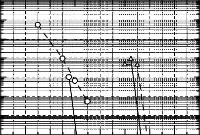
The simulation parameters for speech are shown in Table 5. The BER results are shown in Figure 27. The Eb/N0 values presented in Figure 27 include all the overheads needed for control channels.
Table 5 - Simulation parameters for speech
Environment |
(O) |
(P) |
(V) |
|
|
|
|
Delay profile |
Office A |
Pedestrian A |
Vehicular A |
|
|
|
|
Mobile speed |
3[km/h] |
3[km/h] |
120[km/h] |
|
|
|
|
UL/DL |
both |
both |
both |
|
|
|
|
Antenna diversity |
2 branches |
2 branches |
2 branches |
|
|
|
|
Link level bit rate [kbps] |
12.1[kbps] |
12.1[kbps] |
12.1[kbps] |
|
|
|
|
Information bit rate [kbps] |
8[kbps] |
8[kbps] |
8[kbps] |
|
|
|
|
Modulation |
FDDQPSK |
FDDQPSK |
FDDQPSK |
|
|
|
|
Convolutional coding |
K = 7, R = 1/3 |
K = 7, R = 1/3 |
K = 7, R = 1/3 |
|
|
|
|
Interleaver length (CC) |
18.4[ms](16hop) |
18.4[ms](16hop) |
18.4[ms](16hop) |
|
|
|
|
RS coding |
No |
No |
No |
|
|
|
|
Interleaver length (RS) |
N/A |
N/A |
N/A |
|
|
|
|
Time slot usage |
1(1/4) |
1(1/4) |
1(1/4) |
|
|
|
|
Band slot usage |
1(100[kHz]) |
1(100[kHz]) |
1(100[kHz]) |
|
|
|
|
Frequency hopping bandwidth |
12.8[MHz] |
12.8[MHz] |
12.8[MHz] |
|
|
|
|
Power Control |
No |
No |
No |
|
|
|
|
|
|
|
|
Required. Average .received |
10.0[dB] |
11.2[dB] |
5.6[dB] |
Eb/No[dB] @BER=10^(-3) |
|
|
|
|
|
|
|

UMTS 30.06 version 3.0.0 |
|
|
227 |
|
|
TR 101 146 V3.0.0 (1997-12) |
|||
B.E.R. |
1 |
|
|
|
|
|
|
|
|
|
|
|
|
|
|
|
|
|
|
0.01 |
|
|
|
|
|
|
|
|
|
0.0001 |
|
|
|
|
|
|
|
|
|
|
|
|
|
Vehicular |
|
|
|
|
|
1e-06 |
|
|
Office |
|
|
|
|
|
|
|
|
Pedestrian |
|
|
|
|
|||
|
|
|
|
|
|
|
|
||
|
0 |
2 |
4 |
6 |
8 |
10 |
12 |
14 |
16 |
|
|
|
|
|
|
|
Eb/No[dB] |
||
Figure 27: Eb/No vs BER (SPEECH)
10.2 LCD 144 Simulation
The simulation parameters for LCD 144 are shown in Table 6. In order to achieve the low bit error rates required RS error coding is applied. The details of the RS coding is shown in Table 6. The BER results are shown in Figure 28.
Table 6: Simulation parameters for LCD 144
Environment |
(O) |
(P) |
(V) |
|
|
|
|
Delay profile |
Office A |
Pedestrian A |
Vehicular A |
|
|
|
|
Mobile speed |
3[km/h] |
3[km/h] |
120[km/h] |
|
|
|
|
UL/DL |
both |
both |
both |
|
|
|
|
Antenna diversity |
2 branches |
2 branches |
2 branches |
|
|
|
|
Link level bit rate [kbps] |
163[kbps] |
163[kbps] |
163[kbps] |
|
|
|
|
Information bit rate [kbps] |
144[kbps] |
144[kbps] |
144[kbps] |
|
|
|
|
Modulation |
FDDQPSK |
FDDQPSK |
FDDQPSK |
|
|
|
|
Convolutional coding |
K = 7, R = 1/3 |
K = 7, R = 1/3 |
K = 7, R = 1/3 |
|
|
|
|
Interleaver length (CC) |
147.2[ms] (64hop) |
147.2[ms] (64hop) |
147.2[ms] (64hop) |
|
|
|
|
RS coding |
GF(255)(40,36) |
GF(255)(40,36) |
GF(255)(40,36) |
|
|
|
|
Interleaver length (RS) |
144[ms] |
144[ms] |
144[ms] |
|
|
|
|
Time slot usage |
7(7/8) |
7(7/8) |
7(7/8) |
|
|
|
|
Band slot usage |
4(400[kHz]) |
4(400[kHz]) |
4(400[kHz]) |
|
|
|
|
Frequency hopping bandwidth |
12.8[MHz] |
12.8[MHz] |
12.8[MHz] |
|
|
|
|
Power control |
No |
No |
No |
|
|
|
|
|
|
|
|
Required. Average .received |
|
10.0[dB] |
5.9[dB] |
Eb/No[dB] @BER=10^(-6) |
|
|
|
|
|
|
|
UMTS 30.06 version 3.0.0 |
228 |
TR 101 146 V3.0.0 (1997-12) |
B.E.R. |
1 |
|
|
|
|
|
|
|
|
|
|
|
|
|
|
|
|
|
|
0.01 |
|
Vehicular |
|
|
|
|
|
||
|
w/o RS |
|
|
Pedestrian |
|
||||
|
|
|
|
|
|
|
|
||
|
|
|
|
|
|
|
w/o RS |
|
|
0.0001 |
|
|
|
Pedestrian |
|
|
|
||
|
|
|
|
|
|
|
|
||
|
|
|
|
|
with RS |
|
|
|
|
1e-06 |
|
|
Vehicular |
|
|
|
|
||
|
|
|
|
with RS |
|
|
|
|
|
|
0 |
2 |
4 |
6 |
8 |
10 |
12 |
14 |
16 |
|
|
|
|
|
|
|
Eb/No[dB] |
||
Figure 28: Eb/No vs BER (LCD 144)
10.3 LCD 384 Simulation
The simulation parameters for LCD 384 are shown in Table 7. In order to achieve the low bit error rates required RS error coding is applied. The details of the RS coding is shown in Table 7. The BER results are shown in Figure 29.
Table 7: Link Level Simulation parameters for LCD 384
Environment |
(O) |
(P) |
(V) |
|
|
|
|
Delay profile |
Office A |
Pedestrian A |
Vehicular A |
|
|
|
|
Mobile speed |
3[km/h] |
3[km/h] |
120[km/h] |
|
|
|
|
UL/DL |
both |
both |
both |
|
|
|
|
Antenna diversity |
2 branches |
2 branches |
2 branches |
|
|
|
|
Link level bit rate [kbps] |
396[kbps] |
396[kbps] |
396[kbps] |
|
|
|
|
Information bit rate [kbps] |
384[kbps] |
384[kbps] |
384[kbps] |
|
|
|
|
Modulation |
FDDQPSK |
FDDQPSK |
FDDQPSK |
|
|
|
|
Convolutional coding |
K = 7, R = 1/2.5 |
K = 7, R = 1/2.5 |
K = 7, R = 1/2.5 |
|
|
|
|
Interleaver length (CC) |
147.2[ms] (64hop) |
147.2[ms] (64hop) |
147.2[ms] (64hop) |
|
|
|
|
RS Coding |
GF(255)(40,36) |
GF(255)(40,36) |
GF(255)(80,72) |
|
|
|
|
Interleaver length (RS) |
144[ms] |
144[ms] |
144[ms] |
|
|
|
|
Time slot usage |
7(7/8) |
7(7/8) |
7(7/8) |
|
|
|
|
Band slot usage |
8(800[kHz]) |
8(800[kHz]) |
8(800[kHz]) |
|
|
|
|
Frequency hopping bandwidth |
12.8[MHz] |
12.8[MHz] |
12.8[MHz] |
|
|
|
|
Power control |
No |
No |
No |
|
|
|
|
|
|
|
|
Required. Average .received |
11.3[dB] |
|
5.8[dB] |
Eb/No[dB] @BER=10^(-6) |
|
|
|
|
|
|
|


UMTS 30.06 version 3.0.0 |
230 |
TR 101 146 V3.0.0 (1997-12) |
||
|
|
|
|
|
|
Time slot usage |
3(3/4) |
3(3/4) |
3(3/4) |
|
|
|
|
|
|
Band slot usage |
8(800[kHz]) |
8(800[kHz]) |
8(800[kHz]) |
|
|
|
|
|
|
Frequency hopping bandwidth |
12.8[MHz] |
12.8[MHz] |
12.8[MHz] |
|
|
|
|
|
|
Power control |
No |
No |
No |
|
|
|
|
|
|
|
|
|
|
|
Required. Average .received |
7.0[dB] |
7.8[dB] |
5.2[dB] |
|
Eb/No[dB] @BLER=10^(-1) |
|
|
|
|
|
|
|
|
Table 9: Simulation parameters for UUD144 Mode A
Environment |
(O) |
(P) |
(V) |
|
|
|
|
Delay profile |
Office A |
Pedestrian A |
Vehicular A |
|
|
|
|
Mobile speed |
3[km/h] |
3[km/h] |
120[km/h] |
|
|
|
|
UL/DL |
both |
both |
both |
|
|
|
|
Antenna diversity |
2 branches |
2 branches |
2 branches |
|
|
|
|
Link level bit rate [kbps] |
637[kbps] |
637[kbps] |
637[kbps] |
|
|
|
|
Information bit rate [kbps] |
208[kbps] |
208[kbps] |
208[kbps] |
|
|
|
|
Modulation |
FDDQPSK |
FDDQPSK |
FDDQPSK |
|
|
|
|
Convolutional coding |
K = 7, R = 1/3 |
K = 7, R = 1/3 |
K = 7, R = 1/3 |
|
|
|
|
Interleaver length (CC) |
18.4[ms] (16hop) |
18.4[ms] (16hop) |
18.4[ms] (16hop) |
|
|
|
|
Data block |
320[bits] |
320[bits] |
320[bits] |
|
|
|
|
CRC |
16[bits] |
16[bits] |
16[bits] |
|
|
|
|
RS coding |
N/A |
N/A |
N/A |
|
|
|
|
Interleaver length (RS) |
N/A |
N/A |
N/A |
|
|
|
|
Time slot usage |
3(3/4) |
3(3/4) |
3(3/4) |
|
|
|
|
Band slot usage |
4(400[kHz]) |
4(400[kHz]) |
4(400[kHz]) |
|
|
|
|
Frequency hopping bandwidth |
12.8[MHz] |
12.8[MHz] |
12.8[MHz] |
|
|
|
|
Power control |
No |
No |
No |
|
|
|
|
|
|
|
|
Required. Average .received |
7.0[dB] |
7.8[dB] |
5.2[dB] |
Eb/No[dB] @BLER=10^(-1) |
|
|
|
|
|
|
|