


Introduction
1.7 ORGANIZATION OF DATA IN REGISTERS
The following paragraphs describe data organization within the data, address, and control registers.
1.7.1 Organization of Integer Data Formats in Registers
Each integer data register is 32 bits wide. Byte and word operands occupy the lower 8- and
16-bit portions of integer data registers, respectively. Longword operands occupy the entire
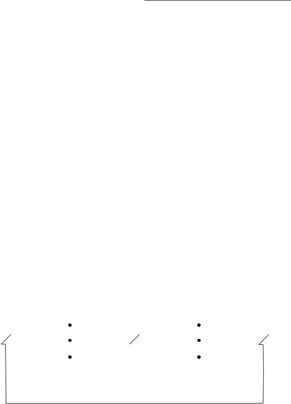
32 bits of integer data registers. A data register that is either a source or destination operand only uses or changes the appropriate lower 8 or 16 bits (in byte or word operations, respectively). The remaining high-order portion does not change and goes unused. The address of the least significant bit (LSB) of a long-word integer is zero, and the MSB is 31. For bit fields, the address of the MSB is zero, and the LSB is the width of the register minus one (the offset). If the width of the register plus the offset is greater than 32, the bit field wraps around within the register. Figure 1-18 illustrates the organization of various data formats in the data registers.
An example of a quad word is the product of a 32-bit multiply or the quotient of a 32-bit divide operation (signed and unsigned). Quad words may be organized in any two integer data registers without restrictions on order or pairing. There are no explicit instructions for the management of this data format, although the MOVEM instruction can be used to move a quad word into or out of registers.
Binary-coded decimal (BCD) data represents decimal numbers in binary form. Although there are many BCD codes, the BCD instructions of the M68000 family support two formats, packed and unpacked. In these formats, the LSBs consist of a binary number having the numeric value of the corresponding decimal number. In the unpacked BCD format, a byte defines one decimal number that has four LSBs containing the binary value and four undefined MSBs. Each byte of the packed BCD format contains two decimal numbers; the least significant four bits contain the least significant decimal number and the most significant four bits contain the most significant decimal number.
MOTOROLA |
M68000 FAMILY PROGRAMMER’S REFERENCE MANUAL |
1-25 |

Introduction
.
31 |
30 |
|
|
|
|
|
1 |
0 |
||
MSB |
|
|
|
|
|
|
|
|
|
LSB |
|
|
|
|
|
|
|
|
|
|
|
31 |
|
|
|
|
|
|
7 |
|
0 |
|
|
NOT USED |
|
|
MSB |
|
LSB |
||||
|
|
|
|
|
|
|
|
|
|
|
31 |
|
|
15 |
|
|
|
|
|
0 |
|
|
NOT USED |
|
MSB |
|
|
LOW-ORDER WORD |
LSB |
|||
|
|
|
|
|
|
|
|
|
|
|
31 |
|
|
|
|
|
|
|
|
|
0 |
MSB |
|
|
LONG WORD |
|
|
|
|
LSB |
||
|
|
|
|
|
|
|
|
|
|
|
63 |
|
|
|
|
|
|
|
|
|
32 |
MSB |
|
|
ANY DX |
|
|
|
|
|
||
|
|
|
|
|
|
|
|
|
|
|
31 |
|
|
|
|
|
|
|
|
|
0 |
|
|
|
ANY DY |
|
|
|
|
LSB |
||
|
|
|
|
|
|
|
|
|
|
|
31 |
|
|
|
|
|
|
|
|
|
0 |
|
OFFSET |
|
WIDTH* |
|
|
|
|
|
||
|
|
|
|
|
|
|
|
|
|
|
31 |
8 |
|
7 |
|
|
4 |
3 |
|
|
0 |
|
|
|
|
|
|
|
|
|
||
|
|
|
UNDEFINED |
|
LEAST SIGNIFICANT DIGIT |
|||||
|
|
|
|
|
|
|
|
|
|
|
31 |
8 |
|
7 |
|
|
4 |
3 |
|
|
0 |
|
|
|
MOST SIGNIFICANT DIGIT |
|
LEAST SIGNIFICANT DIGIT |
|||||
|
|
|
|
|
|
|
|
|
|
|
* IF WIDTH + OFFSET > 32, BIT FIELD WRAPS AROUND WITHIN THE REGISTER.
BIT (0 < MODULO (OFFSET) < 31,OFFSET OF 0 = MSB)
BYTE
16-BIT WORD
LONG WORD
QUAD WORD
BIT FIELD (0 < OFFSET < 32, 0 < WIDTH < 32)
UNPACKED BCD
PACKED BCD
Figure 1-18. Organization of Integer Data Formats in Data Registers
Because address registers and stack pointers are 32 bits wide, address registers cannot be used for byte-size operands. When an address register is a source operand, either the loworder word or the entire long-word operand is used, depending upon the operation size. When an address register is the destination operand, the entire register becomes affected, despite the operation size. If the source operand is a word size, it is sign-extended to 32 bits and then used in the operation to an address register destination. Address registers are primarily for addresses and address computation support. The instruction set includes instructions that add to, compare, and move the contents of address registers. Figure 1-19 illustrates the organization of addresses in address registers.
31 |
16 15 |
0 |
|
SIGN-EXTENDED |
|
|
16-BIT ADDRESS OPERAND |
|
|
|
|
31 |
|
|
0 |
|
|
|
|
|
FULL 32-BIT ADDRESS OPERAND |
|
|
|
|
|
|
Figure 1-19. Organization of Integer Data Formats in Address Registers
1-26 |
M68000 FAMILY PROGRAMMER’S REFERENCE MANUAL |
MOTOROLA |
Introduction
Control registers vary in size according to function. Some control registers have undefined bits reserved for future definition by Motorola. Those particular bits read as zeros and must be written as zeros for future compatibility.
All operations to the SR and CCR are word-size operations. For all CCR operations, the upper byte is read as all zeros and is ignored when written, despite privilege mode. The alternate function code registers, supervisor function code (SFC) and data function code (DFC), are 32-bit registers with only bits 0P2 implemented. These bits contain the address space values for the read or write operands of MOVES, PFLUSH, and PTEST instructions. Values transfer to and from the SFC and DFC by using the MOVEC instruction. These are long-word transfers; the upper 29 bits are read as zeros and are ignored when written.
1.7.2 Organization of Integer Data Formats in Memory
The byte-addressable organization of memory allows lower addresses to correspond to higher order bytes. The address N of a long-word data item corresponds to the address of the highest order wordUs MSB. The lower order word is located at address N + 2, leaving the LSB at address N + 3 (see Figure 1-20). Organization of data formats in memory is consistent with the M68000 family data organization. The lowest address (nearest $00000000) is the location of the MSB, with each successive LSB located at the next address (N + 1, N + 2, etc.). The highest address (nearest $FFFFFFFF) is the location of the LSB.
.
31 |
23 |
15 |
7 |
0 |
|
||||
|
|
|
|
|
|
||||
|
|
|
LONG WORD $00000000 |
|
|
||||
|
|
|
|
|
|
|
|
|
|
|
WORD $00000000 |
|
WORD $00000002 |
|
|
||||
|
|
|
|
|
|
|
|
|
|
|
BYTE $00000000 |
|
BYTE $00000001 |
|
BYTE $00000002 |
|
BYTE $00000003 |
|
|
|
|
|
|
|
|
|
|
|
|
|
|
|
LONG WORD $00000004 |
|
|
||||
|
|
|
|
|
|
|
|
|
|
|
WORD $00000004 |
|
WORD $00000006 |
|
|
||||
|
|
|
|
|
|
|
|
|
|
|
BYTE $00000004 |
|
BYTE $00000005 |
|
BYTE $00000006 |
|
BYTE $00000007 |
|
|
|
|
|
|
|
|
|
|
|
|
|
|
|
|
|
|
|
|
|
|
|
|
|
|
|
|
|
|
|
|
|
|
|
|
|
|
|
|
|
|
|
|
LONG WORD $FFFFFFFC |
|
|
||
WORD $FFFFFFFC |
|
WORD $FFFFFFFE |
||||
|
||||||
BYTE $FFFFFFFC |
|
BYTE $FFFFFFFD |
|
BYTE $FFFFFFFE |
|
BYTE $FFFFFFFF |
|
|
|
||||
|
|
|
|
|
|
|
Figure 1-20. Memory Operand Addressing
MOTOROLA |
M68000 FAMILY PROGRAMMER’S REFERENCE MANUAL |
1-27 |

Introduction
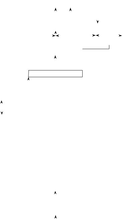
Figure 1-21 illustrates the organization of IU data formats in memory. A base address that selects one byte in memory, the base byte, specifies a bit number that selects one bit, the bit operand, in the base byte. The MSB of the byte is seven.
The following conditions specify a bit field operand:
1.A base address that selects one byte in memory.
2.A bit field offset that shows the leftmost (base) bit of the bit field in relation to the
MSB of the base byte.
3.A bit field width that determines how many bits to the right of the base bit are in the bit field.
The MSB of the base byte is bit field offset 0; the LSB of the base byte is bit field offset 7; and the LSB of the previous byte in memory is bit field offset – 1. Bit field offsets may have values between 2 – 31 to 231 – 1, and bit field widths may range from 1 to 32 bits.
A 16-byte block operand, supported by the MOVE16 instruction, has a block of 16 bytes, aligned to a 16-byte boundary. An address that can point to any byte in the block specifies this operand.
1-28 |
M68000 FAMILY PROGRAMMER’S REFERENCE MANUAL |
MOTOROLA |
|
|
|
|
|
|
|
|
|
|
|
|
|
|
|
|
|
|
|
|
|
|
|
|
|
|
|
|
|
|
|
|
|
|
|
|
|
|
|
|
|
|
|
|
|
|
|
|
|
|
|
|
|
|
|
|
|
|
|
|
Introduction |
|
|
|
|
|
|
|
|
|
|
|
|
|
|
|
|
|
|
|
|
|
|
|
|
|
|
. |
|
|
|
|
|
|
|
|
|
|
|
|
|
|
|
|
|
|
|
|
|
|
|
|
|
|
|
|
|
|
|
|
|
|
|
|
|
|
|
|
|
|
7 |
|
|
|
|
|
0 |
|
|
|
|
|
7 |
|
|
|
|
|
|
|
|
|
|
0 |
|
|
|
|
7 |
|
|
|
|
0 |
|
|
|
7 |
|
|
|
0 |
|
BIT DATA |
|||||||||
|
|
|
|
|
|
|
|
|
|
|
|
|
|
|
|
|
|
|
|
|
|
|
|
|
|
|
|
|
|
|
|
|
|
|
|
|
|
|||||||||||||||||||||||
|
|
|
|
|
|
|
|
|
|
|
|
|
|
|
|
|
|
|
|
|
|
|
|
|
|
|
|
|
|
|
|
|
|
|
|
|
|
|
|
|
|
|
|
|
|
|
|
|
|
|
||||||||||
|
|
|
|
|
|
|
|
|
|
|
BYTE n – 1 |
|
|
|
|
|
|
|
7 6 5 4 |
|
|
3 |
2 1 0 |
|
|
|
|
|
|
BYTE n + 1 |
|
|
|
|
|
|
BYTE n + 2 |
|
|
|||||||||||||||||||||
|
|
|
|
|
|
|
|
|
|
|
|
|
|
|
|
|
|
|
|
|
|
|
|
|
|
|
|
|
|
|
|
|
|
|
|
|
|
|
|
|
|
|
|
|
|
|
|
|
|
|
|
|
|
|
|
|||||
|
|
|
|
|
|
|
|
|
|
|
|
|
|
|
|
|
|
|
|
|
|
|
|
|
|
|
|
|
|
|
|
|
|
|
|
|
|
|
|
|
|
|
|
|
|
|
|
|
|
|
|
|
|
|
|
|||||
|
|
|
|
|
|
|
|
|
|
|
|
|
|
|
ADDRESS |
|
|
BIT |
|
|
|
|
|
|
|
BASE |
BIT |
|
|
|
|
|
|
|
|
|
|
|
|
|||||||||||||||||||||
|
|
|
|
|
|
|
|
|
|
|
|
|
|
|
|
|
|
|
|
|
|
|
|
|
|
NUMBER |
|
|
|
|
|
|
|
|
|
|
|
|
|
|
|
|||||||||||||||||||
|
|
|
|
|
|
|
|
7 |
|
|
|
|
|
0 |
|
|
|
|
|
7 |
|
|
|
|
|
|
|
|
|
|
0 |
|
|
|
|
7 |
|
|
|
|
0 |
|
|
|
7 |
|
|
|
0 |
|
BIT FIELD |
|||||||||
|
|
|
|
|
|
|
|
|
|
|
|
|
|
|
|
|
|
|
|
|
|
|
|
|
|
|
|
|
|
|
|
|
|
|
|
|
|
|
|
|
|
|
|
|
|
|
|
|
|
|
|
|
|
|
|
|
|
|
|
|
|
|
|
|
|
|
|
|
|
|
|
BYTE n – 1 |
|
|
|
|
|
|
|
|
|
|
BYTE n |
|
|
|
|
|
|
|
|
0 |
1 2 3 . . . . w – 1 |
|
|
||||||||||||||||||||||||||
|
|
|
|
|
|
|
|
|
|
|
|
|
|
|
|
|
|
|
|
|
|
|
|
|
|
|
|
|
|
|
|
DATA |
||||||||||||||||||||||||||||
|
|
|
|
|
|
|
|
|
|
|
|
|
|
|
|
|
|
|
|
|
|
|
|
|
|
|
|
|
|
|
|
|
|
|
|
|
|
|
|
|
|
|
|
|
|
|
|
|
|
|
|
|
|
|
|
|
|
|
|
|
|
|
|
|
|
|
|
|
|
|
|
OFFSET |
|
|
|
|
|
|
|
|
|
|
|
|
|
|
|
|
|
OFFSET |
|
|
|
|
|
|
|
|
|
WIDTH |
|
|
|
|
|
|
|||||||||||||||
|
|
|
|
|
|
|
|
|
|
|
|
|
|
|
|
|
|
|
|
|
|
|
|
|
|
|
|
|
|
|
|
|
|
|
|
|
|
|
|
|
|
|
||||||||||||||||||
|
|
|
|
|
|
|
|
|
|
|
. . . – 3 – 2 – 1 |
|
|
|
0 1 2 . . . |
|
|
|
|
|
|
|
|
|
|
|
|
|
|
|
|
|
|
|
|
|
|
|
|
|
|
|
||||||||||||||||||
|
|
|
|
|
|
|
|
|
|
|
|
|
BASE ADDRESS |
|
|
|
|
|
|
|
|
|
|
|
|
|
|
|
|
|
|
|
|
|
|
|
|
|
|
|
|
|
|
|
|
|
||||||||||||||
|
|
|
|
|
|
|
|
7 |
|
|
|
|
|
0 |
|
|
|
|
7 |
|
|
|
|
|
|
|
|
|
|
0 |
|
|
|
|
7 |
|
|
|
|
0 |
|
7 |
|
|
|
0 |
|
BYTE DATA |
||||||||||||
|
|
|
|
|
|
|
|
|
|
|
|
|
|
|
|
|
|
|
|
|
|
|
|
|
|
|
|
|
|
|
|
|
|
|||||||||||||||||||||||||||
|
|
|
|
|
|
|
|
|
|
|
|
|
|
|
|
|
|
|
|
|
|
|
|
|
|
|
|
|
|
|
|
|
|
|
|
|
|
|
|
|
|
|
|
|
|
|
|
|
|
|
|
|
|
|
||||||
|
|
|
|
|
|
|
|
|
|
|
BYTE n – 1 |
|
|
|
|
|
|
|
|
MSB |
BYTE n |
LSB |
|
|
|
BYTE n + 1 |
|
|
|
|
|
|
BYTE n + 2 |
|
|
|||||||||||||||||||||||||
|
|
|
|
|
|
|
|
|
|
|
|
|
|
|
|
|
|
|
|
|
|
|
|
|
|
|
|
|
|
|
|
|
|
|
|
|
|
|
|
|
|
|
|
|
|
|
|
|
|
|
|
|
|
|
|
|||||
|
|
|
|
|
|
|
|
|
|
|
|
|
|
|
|
|
|
|
|
|
|
|
|
|
|
|
|
|
|
|
|
|
|
|
|
|
|
|
|
|
|
|
|
|
|
|
|
|
|
|
|
|
|
|
|
|||||
|
|
|
|
|
|
|
|
|
|
|
|
|
|
|
ADDRESS |
|
|
|
|
|
|
|
|
|
|
|
|
|
|
|
|
|
|
|
|
|
|
|
|
|
|
|
|
|
|
|
|
|
|
|
||||||||||
|
|
|
7 |
0 |
|
|
|
7 |
|
|
|
|
|
0 |
|
|
|
|
|
|
7 |
|
|
|
|
|
|
|
|
|
|
0 |
|
|
|
|
7 |
|
|
|
|
0 |
|
|
|
|
7 |
|
|
|
0 |
|
|
|||||||
|
|
|
|
|
|
|
|
|
|
|
|
|
|
|
|
|
|
|
|
|
|
|
|
|
||||||||||||||||||||||||||||||||||||
|
|
|
|
|
|
|
|
|
|
|
|
|
|
|
|
|
|
|
|
|
|
|
|
|
|
|
|
|
|
|
|
|
|
|
|
|
|
|
|
|
|
|
|
|
|
|
|
|
|
|
|
|
|
|
|
|
|
|||
|
|
|
|
|
BYTE n – 1 |
|
|
|
|
|
|
|
WORD INTEGER |
|
|
|
|
|
|
|
|
|
|
|
|
|
|
BYTE n + 2 |
|
|
|
|
|
|
BYTE n + 3 |
|
|
WORD DATA |
||||||||||||||||||||||
|
|
|
|
|
|
|
|
|
|
|
|
|
|
|
|
|
|
|
|
|
|
|
|
|
|
|
|
|
|
|
|
|
|
|
|
|
|
|
|
|
|
|
|
|
|
|
|
|
|
|
|
|
|
|
|
|
|
|
|
|
|
|
|
|
|
|
|
|
|
|
|
|
|
|
|
|
|
|
|
|
|
|
|
|
|
|
|
|
|
|
|
|
|
|
|
|
|
|
|
|
|
|
|
|
|
|
|
|
|
|
|
|
|
|
|
|
|
|
|
|
|
|
|
|
|
|
ADDRESS |
|
|
|
|
|
|
|
|
|
|
|
|
|
|
|
|
|
|
|
|
|
|
|
|
|
|
|
|
|
|
|
|
|
|
|
|
|
|
|
|
|
|
|
|
|
||||||||||
7 |
0 |
|
|
|
7 |
0 |
|
|
|
7 |
|
|
|
|
|
0 |
|
|
|
|
|
|
7 |
|
|
|
|
|
|
|
|
|
|
0 |
|
|
|
|
7 |
|
|
|
|
0 |
|
|
|
|
|
7 |
|
|
|
0 |
|
LONG-WORD |
||||
|
|
|
|
|
|
|
|
|
|
|
|
|
|
|
|
|
|
|
|
|
|
|
|
|
|
|||||||||||||||||||||||||||||||||||
|
BYTE n – 1 |
|
|
|
|
|
|
|
|
|
LONG-WORD INTEGER |
|
|
|
|
|
|
|
|
|
|
|
|
|
|
|
|
|
|
|
|
BYTE n + 4 |
|
|
||||||||||||||||||||||||||
|
|
|
|
|
|
|
|
|
|
|
|
|
|
|
|
|
|
|
|
|
|
|
|
|
|
|
|
|
|
|
|
DATA |
||||||||||||||||||||||||||||
|
|
|
|
|
|
|
|
|
|
|
|
|
|
|
|
|
|
|
|
|
|
|
|
|
|
|
|
|
|
|
|
|
|
|
|
|
|
|
|
|
|
|
|
|
|
|
|
|
|
|
|
|
|
|
|
|
|
|
|
|
|
|
|
|
|
|
|
|
|
|
|
|
|
|
|
|
|
|
|
|
|
|
|
|
|
|
|
|
|
|
|
|
|
|
|
|
|
|
|
|
|
|
|
|
|
|
|
|
|
|
|
|
|
|
|
|
|
|
|
|
|
|
|
|
|
|
|
|
|
|
|
|
|
|
|
|
|
|
|
|
|
|
|
|
|
|
|
|
|
|
|
|
|
|
|
|
|
|
|
|
|
|
|
|
|
|
|
|
|
|
|
|
|
|
|
|
|
|
|
|
|
|
|
ADDRESS |
|
|
|
|
|
|
|
|
|
|
|
|
|
|
|
|
|
|
|
|
|
|
|
|
|
|
|
|
|
|
|
|
|
|
|
|
|
|
|
|
|
|
|
|
|
|
|
|
|
|
|
|
|
|
|
||||
7 |
0 |
|
|
|
|
0 |
|
7 |
|
|
|
|
|
0 |
|
|
|
|
7 |
|
|
|
|
|
|
|
|
|
|
0 |
|
|
|
7 |
|
|
|
|
0 |
|
|
|
|
7 |
|
|
|
0 |
|
|
||||||||||
|
|
|
7 |
|
|
|
|
|
|
|
|
|
|
|
|
|
|
|
|
|
|
|
|
|
|
|
|
|
|
|
|
|
|
|
|
|
|
|
|
|
||||||||||||||||||||
|
|
|
|
|
|
|
|
|
|
|
|
|
|
|
|
|
|
|
|
|
|
|
|
|
|
|
|
|
|
|
|
|
|
|
|
|
|
|
|
|||||||||||||||||||||
|
BYTE n – 1 |
|
|
|
|
|
|
|
|
|
QUAD-WORD INTEGER |
|
|
|
|
|
|
|
|
|
|
|
|
|
|
|
|
|
|
|
|
|
|
|
|
|
|
|
|
QUAD-WORD |
||||||||||||||||||||
|
|
|
|
|
|
|
|
|
|
|
|
|
|
|
|
|
|
|
|
|
|
|
|
|
|
|
|
|
|
|
|
|
|
|
|
|
|
DATA |
||||||||||||||||||||||
|
|
|
|
|
|
|
|
|
|
|
|
|
|
|
|
|
|
|
|
|
|
|
|
|
|
|
|
|
|
|
|
|
BYTE n + 8 |
|
||||||||||||||||||||||||||
|
|
|
|
|
|
|
|
|
|
|
|
|
|
|
|
|
|
|
|
|
|
|
|
|
|
|
|
|
|
|
|
|
|
|
|
|
|
|
|
|
|
|
|
|
|
|
|
|
|
|
|
|
|
|
|
|
|
|||
|
|
|
|
|
|
|
|
|
|
|
|
|
|
|
|
|
|
|
|
|
|
|
|
|
|
|
|
|
|
|
|
|
|
|
|
|
|
|
|
|
|
|
|
|
|
|
|
|
|
|
|
|
|
|
|
|
|
|||
7 |
0 |
|
7 |
0 |
|
7 |
|
|
|
|
|
0 |
|
|
|
|
7 |
|
|
|
|
|
|
|
|
|
|
0 |
|
|
|
7 |
|
|
|
|
0 |
|
|
7 |
|
|
|
0 |
|
|
||||||||||||||
|
|
|
|
|
|
|
|
|
|
|
|
|
|
|
|
|
|
|
|
|
|
|
|
|
|
|
|
|
|
|
|
|||||||||||||||||||||||||||||
|
BYTE n – 1 |
|
|
|
|
|
|
|
|
|
|
|
16-BYTE BLOCK |
|
|
|
|
|
|
|
|
|
|
|
|
|
|
|
|
|
|
|
|
|
|
|
|
|
|
|
|
|
|
|
|
|
|
|||||||||||||
|
|
|
|
|
|
|
|
|
|
|
|
|
|
|
|
|
|
|
|
|
|
|
|
|
|
|
|
|
|
|
|
|
|
|
|
|
|
|
|
|
|
|
|
|
|
|
||||||||||||||
|
|
|
|
|
|
|
|
|
|
|
|
|
|
|
|
|
|
|
|
|
|
|
|
|
|
|
|
|
|
|
|
|
|
|
|
|
|
|
|
|
|
|
|
|
|
|
||||||||||||||
|
|
|
|
|
|
|
|
|
|
|
|
|
(ALIGNED TO |
|
|
|
|
|
|
|
|
|
|
|
|
|
|
|
|
|
|
|
|
|
|
|
|
|
|
|
|
|
|
|
|
|
|
16-BYTE BLOCK |
||||||||||||
|
|
|
|
|
|
|
|
|
|
|
|
|
|
|
16-BYTE |
|
|
|
|
|
|
|
|
|
|
|
|
|
|
|
|
|
|
|
|
|
|
|
|
|
|
|
|
|
|
|
|
|
|
|
||||||||||
|
|
|
|
|
|
|
|
|
|
|
|
|
|
|
|
|
|
|
|
|
|
|
|
|
|
|
|
|
|
|
|
|
|
|
|
|
|
|
|
|
|
|
|
|
|
|
|
|||||||||||||
|
|
|
|
|
|
|
|
|
|
|
|
|
BOUNDARY) |
|
|
|
|
|
|
|
|
|
|
|
|
|
|
|
|
|
|
|
|
|
|
|
|
|
|
|
|
|
|
|
|
|
|
|
||||||||||||
|
|
|
|
|
|
|
|
|
|
|
|
|
|
|
|
|
|
|
|
|
|
|
|
|
|
|
|
|
|
|
|
|
|
|
|
|
|
|
|
|
|
|
|
|
|
|
|
|
|
|
|
|
|
|
|
|
|
|
|
|
|
|
|
|
|
|
|
|
|
|
|
|
|
|
|
|
|
|
|
|
|
|
|
|
|
|
|
|
|
|
|
|
|
|
|
|
|
|
|
|
|
|
|
|
|
|
|
|
|
|
|
|
|
|
|
BYTE n + 16 |
|
|
|
||
|
|
|
|
|
|
|
|
|
|
|
|
|
|
|
|
|
|
|
|
|
|
|
|
|
|
|
|
|
|
|
|
|
|
|
|
|
|
|
|
|
|
|
|
|
|
|
|
|
|
|
||||||||||
|
|
|
|
|
|
|
|
7 |
|
|
|
|
|
0 |
|
|
|
|
7 |
|
4 |
|
3 |
|
|
0 |
|
|
|
|
|
7 |
|
|
|
|
0 |
|
|
|
|
|
|
7 |
|
|
|
0 |
|
PACKED |
||||||||||
|
|
|
|
|
|
|
|
|
|
|
|
|
|
|
|
|
|
|
|
|
|
|
|
|
|
|
|
|
|
|
|
|
|
|
|
|
|
|||||||||||||||||||||||
|
|
|
|
|
|
|
|
|
|
BYTE n – 1 |
|
|
|
|
|
|
|
|
MSD |
|
|
|
|
|
LSD |
|
|
|
BYTE n + 1 |
|
|
|
|
|
|
BYTE n + 2 |
|
|
BCD |
|||||||||||||||||||||
|
|
|
|
|
|
|
|
|
|
|
|
|
|
|
|
|
|
|
|
|
|
|
|
|
|
|
|
|
|
|
|
|
|
|
|
|
|
|
|
|
|
|
|
|
|
|
|
|
|
|
|
|
|
|
|
|
|
|
|
DATA |
|
|
|
|
|
|
|
|
|
|
|
|
|
|
|
|
|
|
|
|
|
|
|
|
|
|
|
|
|
|
|
|
|
|
|
|
|
|
|
|
|
|
|
|
|
|
|
|
|
|
|
|
|
|
|
|
|
|
|
|
|
|
|
|
|
|
|
|
|
|
|
|
|
|
|
|
|
|
|
|
|
|
|
|
|
|
|
|
|
|
|
|
|
|
|
|
|
|
|
|
|
|
|
|
|
|
|
|
|
|
|
|
|
|
|
|
|
|
|
|
||
|
|
|
|
|
|
|
|
|
|
|
|
|
|
|
|
|
|
|
|
|
|
|
|
|
|
|
|
|
|
|
|
|
|
|
|
|
|
|
|
|
|
|
|
|
|
|
|
|
|
|
|
|
|
|
|
|
|
|
|
|
|
|
|
|
|
|
|
|
|
|
|
|
|
|
|
ADDRESS |
|
|
|
|
|
|
|
|
|
|
|
|
|
|
|
|
|
|
|
|
|
|
|
|
|
|
|
|
|
|
|
|
|
|
|
||||||||||
|
|
|
|
|
|
|
|
7 |
|
|
|
|
|
0 |
|
|
|
|
|
7 |
|
4 |
|
|
3 |
|
|
0 |
|
|
|
7 |
4 |
|
3 |
0 |
|
|
|
7 |
|
|
|
0 |
|
UNPACKED |
||||||||||||||
|
|
|
|
|
|
|
|
|
|
|
|
|
|
|
|
|
|
|
|
|
|
|
|
|
|
|
|
|
|
|
|
|
||||||||||||||||||||||||||||
|
|
|
|
|
|
|
|
|
|
|
|
|
|
|
|
|
|
|
|
|
|
|
|
|
|
|
|
|
|
|
|
|
|
|
|
|
|
|
|
|
|
|
|
|
|
|
|
|
|
|
|
|
|
|
|
|
|
|
|
|
|
|
|
|
|
|
|
|
|
|
|
BYTE n – 1 |
|
|
|
|
|
|
|
|
XX |
|
|
|
|
|
MSD |
|
|
|
|
XX |
|
|
|
LSD |
|
|
|
|
|
|
|
BYTE n + 2 |
|
|
BCD |
||||||||||||||
|
|
|
|
|
|
|
|
|
|
|
|
|
|
|
|
|
|
|
|
|
|
|
|
|
|
|
|
|
|
|
|
|
|
|
|
|
|
|
|
|
|
|
|
|
|
|
|
|
|
|
|
|
|
|
|
|
|
|
|
DATA |
|
|
|
|
|
|
|
|
|
|
|
|
|
|
|
|
|
|
|
|
|
|
|
|
|
|
|
|
|
|
|
|
|
|
|
|
|
|
|
|
|
|
|
|
|
|
|
|
|
|
|
|
|
|
|
|
|
|
|
|
|
|
|
|
|
|
|
|
|
|
|
|
|
|
|
|
|
|
|
|
|
|
|
|
|
|
|
|
|
|
|
|
|
|
|
|
|
|
|
|
|
|
|
|
|
|
|
|
|
|
|
|
|
|
|
|
|
|
|
|
||
|
|
|
|
|
|
|
|
|
|
|
|
|
|
|
|
ADDRESS |
|
|
|
|
|
|
|
|
|
|
|
|
|
|
|
|
|
|
|
|
|
|
|
|
|
|
|
|
|
|
|
|
|
|
|
|||||||||
Figure 1-21. Memory Organization for Integer Operands
MOTOROLA |
M68000 FAMILY PROGRAMMER’S REFERENCE MANUAL |
1-29 |