- •Table of Contents
- •List of Figures
- •List of Tables
- •1.1 Integer Unit User Programming Model
- •1.1.3 Program Counter
- •1.1.4 Condition Code Register
- •1.3 Supervisor Programming Model
- •1.3.2 Status Register
- •1.3.6 Transparent Translation/access Control Registers
- •1.4 Integer Data Formats
- •1.5 Floating-Point Data Formats
- •1.5.1 Packed Decimal Real Format
- •1.5.2 Binary Floating-Point Formats
- •1.6 Floating-Point Data Types
- •1.6.1 Normalized Numbers
- •1.6.2 Denormalized Numbers
- •1.6.3 Zeros
- •1.6.4 Infinities
- •1.6.5 Not-A-Numbers
- •1.6.6 Data Format and Type Summary
- •1.7 Organization of Data in Registers
- •1.7.1 Organization of Integer Data Formats in Registers
- •1.7.2 Organization of Integer Data Formats in Memory
- •1.7.4 Organization of Fpu Data Formats in Registers and Memory
- •2.1 Instruction Format
- •2.2 Effective Addressing Modes
- •2.2.1 Data Register Direct Mode
- •2.2.2 Address Register Direct Mode
- •2.2.3 Address Register Indirect Mode
- •2.2.4 Address Register Indirect with Postincrement Mode
- •2.2.5 Address Register Indirect with Predecrement Mode
- •2.2.6 Address Register Indirect with Displacement Mode
- •2.2.9 Memory Indirect Postindexed Mode
- •2.2.10 Memory Indirect Preindexed Mode
- •2.2.11 Program Counter Indirect with Displacement Mode
- •2.2.14 Program Counter Memory Indirect Postindexed Mode
- •2.2.15 Program Counter Memory Indirect Preindexed Mode
- •2.2.16 Absolute Short Addressing Mode
- •2.2.17 Absolute Long Addressing Mode
- •2.2.18 Immediate Data
- •2.3 Effective Addressing Mode Summary
- •2.4 Brief Extension Word Format Compatibility
- •2.5.1 No Memory Indirect Action Mode
- •2.5.2 Memory Indirect Modes
- •2.6.1 Other Data Structures
- •2.6.1 System Stack
- •2.6.2 Queues
- •3.1 Instruction Summary
- •3.1.1 Data Movement Instructions
- •3.1.2 Integer Arithmetic Instructions
- •3.1.3 Logical Instructions
- •3.1.4 Shift and Rotate Instructions
- •3.1.5 Bit Manipulation Instructions
- •3.1.6 Bit Field Instructions
- •3.1.7 Binary-Coded Decimal Instructions
- •3.1.8 Program Control Instructions
- •3.1.9 System Control Instructions
- •3.1.11 Multiprocessor Instructions
- •3.1.13 Floating-Point Arithmetic Instructions
- •3.2 Integer Unit Condition Code Computation
- •3.3 Instruction Examples
- •3.3.2 Using the Moves Instruction
- •3.3.3 Nested Subroutine Calls
- •3.3.4 Bit Field Instructions
- •3.3.5 Pipeline Synchronization with the Nop Instruction
- •3.4 Floating-Point Instruction Details
- •3.5 Floating-Point Computational Accuracy
- •3.5.1 Intermediate Result
- •3.5.2 Rounding the Result
- •3.6 Floating-Point Postprocessing
- •3.7 Instruction Descriptions
- •8.1 Instruction Format
- •8.1.1 Coprocessor ID Field
- •8.1.2 Effective Address Field
- •8.1.4 Source Specifier Field
- •8.1.5 Destination Register Field
- •8.1.6 Conditional Predicate Field
- •8.1.7 Shift and Rotate Instructions
- •8.1.8 Size Field
- •8.1.9 Opmode Field
- •8.1.10 Address/Data Field
- •8.2 Operation Code Map
- •A.1 MC68000, MC68008, MC68010 Processors
- •A.1.2 MC68000, MC68008, and MC68010 Addressing Modes
- •A.2 MC68020 Processors
- •A.2.1 MC68020 Instruction Set
- •A.2.2 MC68020 Addressing Modes
- •A.3 MC68030 Processors
- •A.3.1 MC68030 Instruction Set
- •A.3.2 MC68030 Addressing Modes
- •A.4 MC68040 Processors
- •A.4.1 MC68040 Instruction Set
- •A.4.2 MC68040 Addressing Modes
- •A.5 MC68881/MC68882 CoProcessors
- •A.5.2 MC68881/MC68882 Addressing Modes
- •A.6 MC68851 Coprocessors
- •A.6.1 MC68851 Instruction Set
- •A.6.2 MC68851 Addressing Modes
- •B.1 Exception Vector Assignments for the M68000 Family
- •B.2 Exception Stack Frames
- •B.3 Floating-Point Stack Frames
- •C.1 S-Record Content
- •C.2 S-Record Types
- •C.3 S-Record Creation

Addressing Capabilities
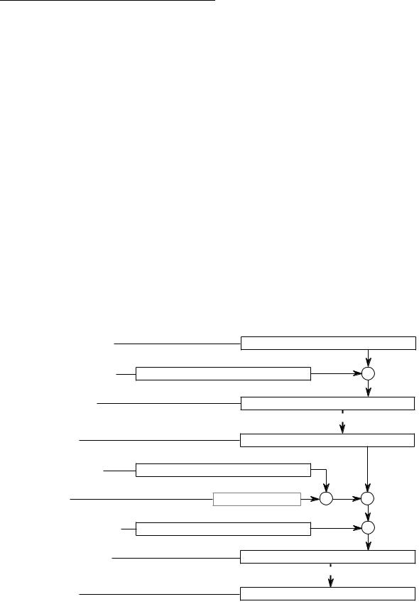
2.2.14 Program Counter Memory Indirect Postindexed Mode
This mode is similar to the mode described in 2.2.9 Memory Indirect Postindexed Mode, but the PC is the base register. Both the operand and operand address are in memory. The processor calculates an intermediate indirect memory address by adding a base displacement to the PC contents. The processor accesses a long word at that address and adds the scaled contents of the index register and the optional outer displacement to yield the effective address. The value of the PC used in the calculation is the address of the first extension word. This is a program reference allowed only for reads.
In the syntax for this mode, brackets enclose the values used to calculate the intermediate memory address. All four user-specified values are optional. The user must supply the assembler notation ZPC (a zero value PC) to show the PC is not used. This allows the user to access the program space without using the PC in calculating the effective address. Both the base and outer displacements may be null, word, or long word. When omitting a displacement or suppressing an element, its value is zero in the effective address calculation.
GENERATION: |
EA = (bd + PC) + Xn.SIZE*SCALE + od |
|
|
ASSEMBLER SYNTAX: |
([bd,PC],Xn.SIZE*SCALE,od) |
|
|
EA MODE FIELD: |
111 |
|
|
EA REGISTER FIELD: |
011 |
|
|
NUMBER OF EXTENSION WORDS: |
1,2,3,4, or 5 |
|
|
|
31 |
|
0 |
PROGRAM COUNTER |
|
CONTENTS |
|
31 |
|
0 |
+ |
BASE DISPLACEMENT |
SIGN-EXTENDED VALUE |
|
|
|
31 |
|
0 |
INTERMEDIATE |
|
CONTENTS |
|
ADDRESS |
|
|
|
|
|
|
|
|
|
POINTS TO |
|
|
31 |
|
0 |
MEMORY |
VALUE AT INDIRECT MEM. ADDRESS IN PROG. SPACE |
||
31 |
|
0 |
|
INDEX REGISTER |
SIGN-EXTENDED VALUE |
|
|
SCALE |
SCALE VALUE |
X |
+ |
31 |
|
0 |
|
OUTER DISPLACEMENT |
SIGN-EXTENDED VALUE |
|
+ |
|
31 |
|
0 |
OPERAND POINTER |
|
CONTENTS |
|
|
|
POINTS TO |
|
MEMORY |
|
OPERAND |
|
2-16 |
M68000 FAMILY PROGRAMMER’S REFERENCE MANUAL |
MOTOROLA |

Addressing Capabilities
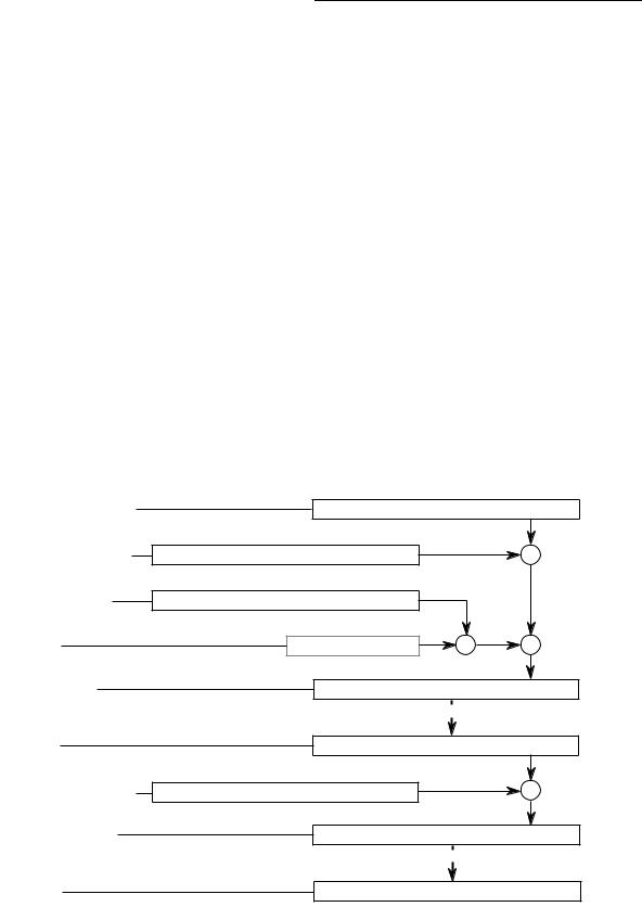
2.2.15 Program Counter Memory Indirect Preindexed Mode
This mode is similar to the mode described in 2.2.10 Memory Indirect Preindexed Mode, but the PC is the base register. Both the operand and operand address are in memory. The processor calculates an intermediate indirect memory address by adding the PC contents, a base displacement, and the scaled contents of an index register. The processor accesses a long word at immediate indirect memory address and adds the optional outer displacement to yield the effective address. The value of the PC is the address of the first extension word. This is a program reference allowed only for reads.
In the syntax for this mode, brackets enclose the values used to calculate the intermediate memory address. All four user-specified values are optional. The user must supply the assembler notation ZPC showing that the PC is not used. This allows the user to access the program space without using the PC in calculating the effective address. Both the base and outer displacements may be null, word, or long word. When omitting a displacement or suppressing an element, its value is zero in the effective address calculation.
|
. |
|
|
GENERATION: |
EA = (bd + PC) + Xn.SIZE*SCALE + od |
|
|
ASSEMBLER SYNTAX: |
([bd,PC,Xn.SIZE*SCALE],od) |
|
|
EA MODE FIELD: |
111 |
|
|
EA REGISTER FIELD: |
011 |
|
|
NUMBER OF EXTENSION WORDS: |
1,2,3,4, or 5 |
|
|
|
31 |
|
0 |
PROGRAM COUNTER |
|
CONTENTS |
|
31 |
|
0 |
+ |
BASE DISPLACEMENT |
SIGN-EXTENDED VALUE |
|
|
31 |
|
0 |
|
INDEX REGISTER |
SIGN-EXTENDED VALUE |
|
|
SCALE |
SCALE VALUE |
X |
+ |
INTERMEDIATE |
31 |
|
0 |
INDIRECT MEMORY ADDRESS |
|
||
ADDRESS |
|
||
|
|
|
|
|
|
POINTS TO |
|
|
31 |
|
0 |
MEMORY |
VALUE AT INDIRECT MEM. ADDRESS IN PROG. SPACE |
||
31 |
|
0 |
+ |
OUTER DISPLACEMENT |
SIGN-EXTENDED VALUE |
|
|
|
31 |
|
0 |
OPERAND POINTER |
|
CONTENTS |
|
|
|
POINTS TO |
|
MEMORY |
|
OPERAND |
|
MOTOROLA |
M68000 FAMILY PROGRAMMER’S REFERENCE MANUAL |
2-17 |

Addressing Capabilities
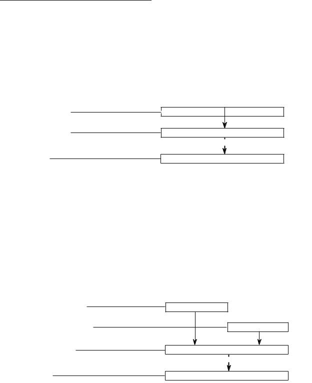
2.2.16 Absolute Short Addressing Mode
In this addressing mode, the operand is in memory, and the address of the operand is in the extension word. The 16-bit address is sign-extended to 32 bits before it is used. .
GENERATION: |
EA GIVEN |
|
|
ASSEMBLER SYNTAX: |
(xxx).W |
|
|
EA MODE FIELD: |
111 |
|
|
EA REGISTER FIELD: |
000 |
|
|
NUMBER OF EXTENSION WORDS: |
1 |
|
|
|
31 |
15 |
0 |
EXTENSION WORD |
SIGN-EXTENDED |
EXTENSION VALUE |
|
|
31 |
|
0 |
OPERAND POINTER |
|
CONTENTS |
|
|
|
POINTS TO |
|
MEMORY |
|
OPERAND |
|
2.2.17 Absolute Long Addressing Mode
In this addressing mode, the operand is in memory, and the operand’s address occupies the two extension words following the instruction word in memory. The first extension word contains the high-order part of the address; the second contains the low-order part of the address. .
GENERATION: |
EA GIVEN |
|
|
ASSEMBLER SYNTAX: |
(xxx).L |
|
|
EA MODE FIELD: |
111 |
|
|
EA REGISTER FIELD: |
001 |
|
|
NUMBER OF EXTENSION WORDS: |
2 |
|
|
|
15 |
0 |
|
FIRST EXTENSION WORD |
|
ADDRESS HIGH |
|
|
|
15 |
0 |
SECOND EXTENSION WORD |
|
|
ADDRESS LOW |
|
31 |
|
0 |
OPERAND POINTER |
|
CONTENTS |
|
|
|
POINTS TO |
|
MEMORY |
|
OPERAND |
|
2-18 |
M68000 FAMILY PROGRAMMER’S REFERENCE MANUAL |
MOTOROLA |
