
- •Table of Contents
- •List of Figures
- •List of Tables
- •1.1 Integer Unit User Programming Model
- •1.1.3 Program Counter
- •1.1.4 Condition Code Register
- •1.3 Supervisor Programming Model
- •1.3.2 Status Register
- •1.3.6 Transparent Translation/access Control Registers
- •1.4 Integer Data Formats
- •1.5 Floating-Point Data Formats
- •1.5.1 Packed Decimal Real Format
- •1.5.2 Binary Floating-Point Formats
- •1.6 Floating-Point Data Types
- •1.6.1 Normalized Numbers
- •1.6.2 Denormalized Numbers
- •1.6.3 Zeros
- •1.6.4 Infinities
- •1.6.5 Not-A-Numbers
- •1.6.6 Data Format and Type Summary
- •1.7 Organization of Data in Registers
- •1.7.1 Organization of Integer Data Formats in Registers
- •1.7.2 Organization of Integer Data Formats in Memory
- •1.7.4 Organization of Fpu Data Formats in Registers and Memory
- •2.1 Instruction Format
- •2.2 Effective Addressing Modes
- •2.2.1 Data Register Direct Mode
- •2.2.2 Address Register Direct Mode
- •2.2.3 Address Register Indirect Mode
- •2.2.4 Address Register Indirect with Postincrement Mode
- •2.2.5 Address Register Indirect with Predecrement Mode
- •2.2.6 Address Register Indirect with Displacement Mode
- •2.2.9 Memory Indirect Postindexed Mode
- •2.2.10 Memory Indirect Preindexed Mode
- •2.2.11 Program Counter Indirect with Displacement Mode
- •2.2.14 Program Counter Memory Indirect Postindexed Mode
- •2.2.15 Program Counter Memory Indirect Preindexed Mode
- •2.2.16 Absolute Short Addressing Mode
- •2.2.17 Absolute Long Addressing Mode
- •2.2.18 Immediate Data
- •2.3 Effective Addressing Mode Summary
- •2.4 Brief Extension Word Format Compatibility
- •2.5.1 No Memory Indirect Action Mode
- •2.5.2 Memory Indirect Modes
- •2.6.1 Other Data Structures
- •2.6.1 System Stack
- •2.6.2 Queues
- •3.1 Instruction Summary
- •3.1.1 Data Movement Instructions
- •3.1.2 Integer Arithmetic Instructions
- •3.1.3 Logical Instructions
- •3.1.4 Shift and Rotate Instructions
- •3.1.5 Bit Manipulation Instructions
- •3.1.6 Bit Field Instructions
- •3.1.7 Binary-Coded Decimal Instructions
- •3.1.8 Program Control Instructions
- •3.1.9 System Control Instructions
- •3.1.11 Multiprocessor Instructions
- •3.1.13 Floating-Point Arithmetic Instructions
- •3.2 Integer Unit Condition Code Computation
- •3.3 Instruction Examples
- •3.3.2 Using the Moves Instruction
- •3.3.3 Nested Subroutine Calls
- •3.3.4 Bit Field Instructions
- •3.3.5 Pipeline Synchronization with the Nop Instruction
- •3.4 Floating-Point Instruction Details
- •3.5 Floating-Point Computational Accuracy
- •3.5.1 Intermediate Result
- •3.5.2 Rounding the Result
- •3.6 Floating-Point Postprocessing
- •3.7 Instruction Descriptions
- •8.1 Instruction Format
- •8.1.1 Coprocessor ID Field
- •8.1.2 Effective Address Field
- •8.1.4 Source Specifier Field
- •8.1.5 Destination Register Field
- •8.1.6 Conditional Predicate Field
- •8.1.7 Shift and Rotate Instructions
- •8.1.8 Size Field
- •8.1.9 Opmode Field
- •8.1.10 Address/Data Field
- •8.2 Operation Code Map
- •A.1 MC68000, MC68008, MC68010 Processors
- •A.1.2 MC68000, MC68008, and MC68010 Addressing Modes
- •A.2 MC68020 Processors
- •A.2.1 MC68020 Instruction Set
- •A.2.2 MC68020 Addressing Modes
- •A.3 MC68030 Processors
- •A.3.1 MC68030 Instruction Set
- •A.3.2 MC68030 Addressing Modes
- •A.4 MC68040 Processors
- •A.4.1 MC68040 Instruction Set
- •A.4.2 MC68040 Addressing Modes
- •A.5 MC68881/MC68882 CoProcessors
- •A.5.2 MC68881/MC68882 Addressing Modes
- •A.6 MC68851 Coprocessors
- •A.6.1 MC68851 Instruction Set
- •A.6.2 MC68851 Addressing Modes
- •B.1 Exception Vector Assignments for the M68000 Family
- •B.2 Exception Stack Frames
- •B.3 Floating-Point Stack Frames
- •C.1 S-Record Content
- •C.2 S-Record Types
- •C.3 S-Record Creation

Processor Instruction Summary
Table A-12. MC68881/MC68882 Instruction Set
Mnemonic |
Description |
|
|
FSQRT |
Floating-Point Square Root |
FSUB |
Floating-Point Subtract |
FTAN |
Tangent |
FTANH |
Hyperbolic Tangent |
FTENTOX |
Floating-Point 10x |
FTRAPcc |
Floating-Point Trap On Condition |
FTST |
Floating-Point Test |
FTWOTOX |
Floating-Point 2x |
|
|
A.5.2 MC68881/MC68882 Addressing Modes
The MC68881/MC68882 does not perform address calculations. When the floating-point coprocessor instructs the processor to transfer an operand via the coprocessor interface, the processor performs the addressing mode calculation requested in the instruction.
A.6 MC68851 COPROCESSORS
The following paragraphs provide information on the MC68851 instruction set and addressing modes.
A.6.1 MC68851 Instruction Set
Table A-13 lists the instructions used with the MC68851 coprocessor.
|
Table A-13. MC68851 Instruction Set |
|
|
|
|
Mnemonic |
|
Description |
|
|
|
PBcc |
|
Branch on PMMU Condition |
PDBcc |
|
Test, Decrement, and Branch on PMMU Condition |
PFLUSH |
|
Flush Entry(ies) in the ATCs |
PFLUSHA |
|
Flush Entry(ies) in the ATCs |
PFLUSHR |
|
Flush Entry(ies) in the ATCs and RPT Entries |
PFLUSHS |
|
Flush Entry(ies) in the ATCs |
PLOAD |
|
Load an Entry into the ATC |
PMOVE |
|
Move PMMU Register |
PRESTORE |
|
PMMU Restore Function |
PSAVE |
|
PMMU Save Function |
PScc |
|
Set on PMMU Condition |
PTEST |
|
Test a Logical Address |
PTRAPcc |
|
Trap on PMMU Condition |
PVALID |
|
Validate a Pointer |
|
|
|
A.6.2 MC68851 Addressing Modes
The MC68851 supports the same addressing modes as the MC68020 (see Table A-7).
MOTOROLA |
MC68000 FAMILY PROGRAMMER’S REFERENCE MANUAL |
A-31 |
APPENDIX B
EXCEPTION PROCESSING REFERENCE
This appendix provides a quick reference for system programmers who are already familiar with the stack frames. For more detail, please refer to the appropriate userOs manual.
B.1 EXCEPTION VECTOR ASSIGNMENTS FOR THE M68000 FAMILY
Table B-1 lists all vector assignments up to and including the MC68040 and its derivatives.
Many of these vector assignments are processor specific. For instance, vector 13, the coprocessor protocol violation vector, only applies to the MC68020, MC68EC020, MC68030, and MC68EC030. Refer to the appropriate user’s manual to determine which exception type is applicable to a specific processor.
MOTOROLA |
MC68000 FAMILY PROGRAMMER’S REFERENCE MANUAL |
B-1 |

Exception Processing Reference
Table B-1. Exception Vector Assignments for the M68000 Family
Vector |
Vector |
|
Number( s) |
Offset (Hex) |
Assignment |
|
|
|
0 |
000 |
Reset Initial Interrupt Stack Pointer |
1 |
004 |
Reset Initial Program Counter |
2 |
008 |
Access Fault |
3 |
00C |
Address Error |
|
|
|
4 |
010 |
Illegal Instruction |
5 |
014 |
Integer Divide by Zero |
6 |
018 |
CHK, CHK2 Instruction |
7 |
01C |
FTRAPcc, TRAPcc, TRAPV Instructions |
|
|
|
8 |
020 |
Privilege Violation |
9 |
024 |
Trace |
10 |
028 |
Line 1010 Emulator (Unimplemented A- Line Opcode) |
11 |
02C |
Line 1111 Emulator (Unimplemented F-Line Opcode) |
|
|
|
12 |
030 |
(Unassigned, Reserved) |
13 |
034 |
Coprocessor Protocol Violation |
14 |
038 |
Format Error |
15 |
03C |
Uninitialized Interrupt |
|
|
|
16–23 |
040–05C |
(Unassigned, Reserved) |
|
|
|
24 |
060 |
Spurious Interrupt |
25 |
064 |
Level 1 Interrupt Autovector |
26 |
068 |
Level 2 Interrupt Autovector |
27 |
06C |
Level 3 Interrupt Autovector |
|
|
|
28 |
070 |
Level 4 Interrupt Autovector |
29 |
074 |
Level 5 Interrupt Autovector |
30 |
078 |
Level 6 Interrupt Autovector |
31 |
07C |
Level 7 Interrupt Autovector |
|
|
|
32–47 |
080–0BC |
TRAP #0 D 15 Instruction Vectors |
|
|
|
48 |
0C0 |
FP Branch or Set on Unordered Condition |
49 |
0C4 |
FP Inexact Result |
50 |
0C8 |
FP Divide by Zero |
51 |
0CC |
FP Underflow |
|
|
|
52 |
0D0 |
FP Operand Error |
53 |
0D4 |
FP Overflow |
54 |
0D8 |
FP Signaling NAN |
55 |
0DC |
FP Unimplemented Data Type (Defined for MC68040) |
|
|
|
56 |
0E0 |
MMU Configuration Error |
57 |
0E4 |
MMU Illegal Operation Error |
58 |
0E8 |
MMU Access Level Violation Error |
|
|
|
59–63 |
0ECD0FC |
(Unassigned, Reserved) |
|
|
|
64–255 |
100D3FC |
User Defined Vectors (192) |
|
|
|
B-2 |
MC68000 FAMILY PROGRAMMER’S REFERENCE MANUAL |
MOTOROLA |
Exception Processing Reference
B.2 EXCEPTION STACK FRAMES
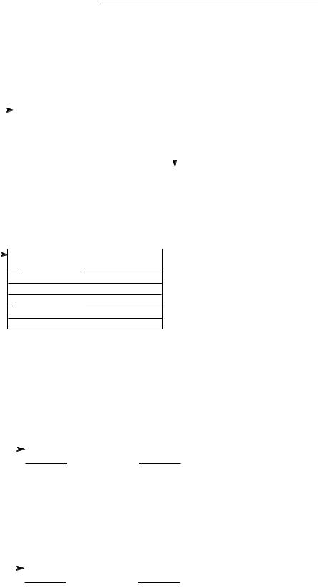
Figures B-1 through B-15 illustrate all exception stack frames for the M68000 family..
|
|
|
|
ODD BYTE |
EVEN BYTE |
|
|
|
7 |
0 |
7 |
0 |
|
|
|||
15 |
|
|
0 |
HIGHER |
||||
SP |
|
|
|
STATUS REGISTER |
|
ADDRESS |
||
|
|
|
||||||
|
|
|
|
PROGRAM COUNTER HIGH |
|
|
|
|
|
|
|
|
|
|
|
||
|
|
|
|
PROGRAM COUNTER LOW |
|
|
|
|
|
|
|
|
|
|
|
|
|
Figure B-1. MC68000 Group 1 and 2 Exception Stack Frame
15 |
5 |
4 |
3 |
2 |
0 |
|||
LOWER |
|
|
|
|
|
|
||
|
|
R/W |
I/N |
FUNCTION CODE |
||||
ADDRESS |
|
|
|
|
||||
HIGH
ACCESS ADDRESS
LOW
INSTRUCTION REGISTER
STATUS REGISTER
PROGRAM COUNTER
HIGH
LOW
R/W (READ/WRITE): WRITE = 0, READ = 1. I/N (INSTRUCTION/NOT): INSTRUCTION = 0, NOT = 1.
Figure B-2. MC68000 Bus or Address Error Exception Stack Frame
|
|
|
15 |
0 |
|
SP |
|
|
|
|
STATUS REGISTER |
|
|
|
|||
+$02 |
|
|
PROGRAM COUNTER |
||
+$06 |
|
|
|||
|
|
|
|
||
|
0 0 0 0 |
|
VECTOR OFFSET |
||
Figure B-3. Four-Word Stack Frame, Format $0
|
|
|
15 |
0 |
|
SP |
|
|
|
STATUS REGISTER |
|
|
|
||||
+$02 |
|
|
PROGRAM COUNTER |
||
+$06 |
|
|
|||
|
|
|
|
||
|
0 0 0 1 |
|
VECTOR OFFSET |
||
Figure B-4. Throwaway Four-Word Stack Frame, Format $1
MOTOROLA |
MC68000 FAMILY PROGRAMMER’S REFERENCE MANUAL |
B-3 |
Exception Processing Reference
|
|
|
15 |
0 |
|
SP |
|
|
|
|
STATUS REGISTER |
|
|
|
|||
+$02 |
|
|
PROGRAM COUNTER |
||
+$06 |
|
|
|||
|
|
|
|
||
|
0 0 1 0 |
|
VECTOR OFFSET |
||
+$08 |
|
|
|
ADDRESS |
|
|
|
|
|
|
|
|
|
|
|
|
|
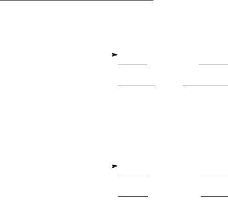
Figure B-5. Six-Word Stack Frame, Format $2
|
|
|
15 |
0 |
|
SP |
|
|
|
|
STATUS REGISTER |
|
|
|
|||
+$02 |
|
|
PROGRAM COUNTER |
||
+$06 |
|
|
|||
|
|
|
|
||
|
0 0 1 0 |
|
VECTOR OFFSET |
||
+$08 |
|
|
EFFECTIVE ADDRESS |
||
|
|
|
|
||
|
|
|
|
|
|
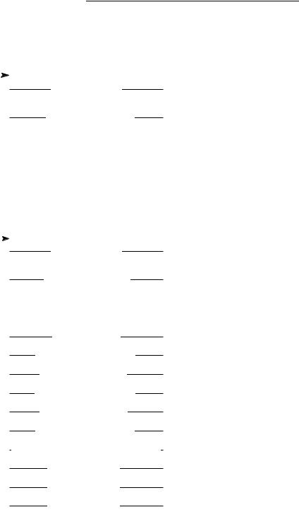
Figure B-6. MC68040 Floating-Point Post-Instruction Stack Frame, Format $3
B-4 |
MC68000 FAMILY PROGRAMMER’S REFERENCE MANUAL |
MOTOROLA |
Exception Processing Reference
|
|
|
15 |
0 |
|
SP |
|
|
|
|
STATUS REGISTER |
|
|
|
|||
+$02 |
|
|
PROGRAM COUNTER |
||
+$06 |
|
|
|||
|
|
|
|
||
|
0 1 0 0 |
|
VECTOR OFFSET |
||
+$08 |
|
|
EFFECTIVE ADDRESS (EA) |
||
|
|
|
|
||
|
|
|
|
||
+$0C |
|
|
PC OF FAULTED |
||
|
|
|
|
|
INSTRUCTION |
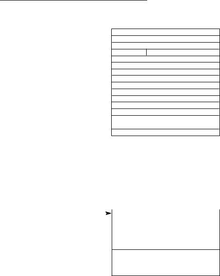
Figure B-7. MC68EC040 and MC68LC040 Floating-Point Unimplemented Stack
Frame, Format $4
|
|
|
15 |
0 |
|||
SP |
|
|
|
|
STATUS REGISTER |
||
|
|
||||||
+$02 |
|
|
|
PROGRAM COUNTER |
|||
|
|
|
|
|
|||
|
|
|
|
|
|
||
+$06 |
|
0 1 1 1 |
|
|
VECTOR OFFSET |
||
+$08 |
|
|
|
EFFECTIVE ADDRESS (EA) |
|||
+$0A |
|
|
|||||
|
|
|
|
||||
+$0C |
|
|
SPECIAL STATUS WORD |
||||
+$0E |
$00 |
|
|
WRITEBACK 3 STATUS (WB3S) |
|||
+$10 |
|
$00 |
|
|
WRITEBACK 2 STATUS (WB2S) |
||
+$12 |
|
$00 |
|
|
WRITEBACK 1 STATUS (WB1S) |
||
+$14 |
|
|
|
FAULT ADDRESS (FA) |
|||
+$18 |
|
|
|
||||
|
|
|
|
|
|||
|
WRITEBACK 3 ADDRESS (WB3A) |
||||||
+$1C |
|||||||
|
|
|
|
||||
|
WRITEBACK 3 DATA (WB3D) |
||||||
+$20 |
|
|
|||||
|
|
|
|
|
|||
|
WRITEBACK 2 ADDRESS (WB2A) |
||||||
+$24 |
|
||||||
|
|
|
|
|
|||
|
|
WRITEBACK 2 DATA (WB2D) |
|||||
+$28 |
|
|
|||||
|
|
|
|
|
|||
|
WRITEBACK 1 ADDRESS (WB1A) |
||||||
+$2C |
|||||||
|
|
|
|
||||
WRITEBACK 1 DATA/PUSH DATA LW0 (WB1D/PD0) |
|||||||
+$30 |
|
||||||
|
|
|
|
|
|||
|
|
|
PUSH DATA LW 1 (PD1) |
||||
+$34 |
|
|
|
||||
|
|
|
|
|
|||
|
|
|
PUSH DATA LW 2 (PD2) |
||||
+$38 |
|
|
|
||||
|
|
|
|
|
|||
|
|
|
PUSH DATA LW 3 (PD3) |
||||
|
|
|
|
|
|||
|
|
|
|
|
|
|
|
Figure B-8. MC68040 Access Error Stack Frame, Format $7
MOTOROLA |
MC68000 FAMILY PROGRAMMER’S REFERENCE MANUAL |
B-5 |
Exception Processing Reference
SP  +$02
+$02
+$06 +$08
+$0C
+$10
+$14 +$16 +$18 $1A
+$50
15 |
0 |
STATUS REGISTER
PROGRAM COUNTER HIGH
PROGRAM COUNTER LOW
1 0 0 0 VECTOR OFFSET
SPECIAL STATUS WORD
FAULT ADDRESS HIGH
FAULT ADDRESS LOW
UNUSED, RESERVED
DATA OUTPUT BUFFER
UNUSED, RESERVED
DATA INPUT BUFFER
UNUSED, RESERVED
INSTRUCTION OUTPUT BUFFER |VERSION| |NUMBER|
INTERNAL INFORMATION, 16 WORDS
NOTE: The stack pointer decrements by 29 words, although only 26 words of information actually write to memory. Motorola reserves the three additional words for future use.
Figure B-9. MC68010 Bus and Address Error Stack Frame, Format $8
|
|
|
15 |
|
|
0 |
|
|||
SP |
|
|
|
|
|
STATUS REGISTER |
||||
|
|
|
|
|||||||
+$02 |
|
|
|
|
|
|
|
|
|
|
|
|
|
PROGRAM COUNTER |
|
|
|
||||
+$06 |
|
|
|
|
|
|
|
|||
|
|
|
|
|
|
|
|
|||
|
|
|
|
|
|
|
|
|
||
|
1 |
0 0 1 |
|
VECTOR OFFSET |
||||||
+$08 |
|
|
|
|
|
|
|
|
|
|
|
|
INSTRUCTION ADDRESS |
|
|
||||||
|
|
|
|
|
|
|||||
|
|
|
|
|
|
|
|
|
|
|
+$0C
INTERNAL REGISTERS
4 WORDS
+$12
Figure B-10. MC68020 Bus and MC68030 Coprocessor Mid-Instruction Stack Frame,
Format $9
B-6 |
MC68000 FAMILY PROGRAMMER’S REFERENCE MANUAL |
MOTOROLA |

Exception Processing Reference
15 |
|
|
|
0 |
|
|||||||
SP |
|
|
|
|
|
|
STATUS REGISTER |
|||||
|
|
|
|
|
||||||||
+$02 |
|
|
|
|
|
|
|
|
|
|
|
|
|
|
|
|
PROGRAM COUNTER |
|
|
|
|
||||
|
|
|
|
|
|
|
|
|
|
|
||
|
|
|
|
|
|
|
|
|
|
|
|
|
|
|
|
|
|
|
|
|
|
|
|
|
|
+$06 |
|
1 |
0 1 0 |
|
VECTOR OFFSET |
|||||||
+$08 |
|
|
|
|
|
INTERNAL REGISTER |
||||||
|
+$0A |
|
|
SPECIAL STATUS REGISTER |
||||||||
|
+$0C |
|
|
INSTRUCTION PIPE STAGE C |
|
|||||||
|
+$0E |
|
|
INSTRUCTION PIPE STATE B |
||||||||
+$10 |
|
|
|
|
|
|
|
|
|
|
|
|
|
|
|
DATA CYCLE FAULT ADDRESS |
|
|
|||||||
+$12 |
|
|
|
|
|
|||||||
|
|
|
|
|
|
|
|
|
|
|
||
|
|
|
|
|
|
|
|
|
|
|
||
+$14 |
|
|
|
|
|
INTERNAL REGISTER |
|
|||||
+$16 |
|
|
|
|
|
INTERNAL REGISTER |
||||||
+$18 |
|
|
|
|
|
|
|
|
|
|
|
|
|
|
|
|
|
DATA OUTPUT BUFFER |
|
|
|
||||
|
+$1A |
|
|
|
|
|
||||||
|
|
|
|
|
|
|
|
|
|
|
||
|
+$1C |
|
|
|
|
INTERNAL REGISTER |
||||||
|
+$1E |
|
|
|
|
INTERNAL REGISTER |
||||||
Figure B-11. MC68020 and MC68030 Short Bus Cycle Stack Frame, Format $A
MOTOROLA |
MC68000 FAMILY PROGRAMMER’S REFERENCE MANUAL |
B-7 |

Exception Processing Reference
|
15 |
|
|
|
|
|
0 |
|
|
||||||||||
SP |
|
|
|
|
|
|
|
|
STATUS REGISTER |
||||||||||
|
|
|
|
|
|
|
|||||||||||||
+$02 |
|
|
|
|
|
|
|
|
|
|
|
|
|
|
|
|
|
|
|
|
|
|
|
|
|
|
|
PROGRAM COUNTER |
|
|
|
|
|
|
|||||
|
|
|
|
|
|
|
|
|
|
|
|
|
|
|
|
|
|||
|
|
|
|
|
|
|
|
|
|
|
|
|
|
|
|
|
|
||
|
|
|
|
|
|
|
|
|
|
|
|
|
|
|
|
|
|
|
|
+$06 1 |
0 1 1 |
|
|
|
VECTOR OFFSET |
||||||||||||||
+$08 |
|
|
|
|
|
|
|
|
|
INTERNAL REGISTER |
|||||||||
|
+$0A |
|
|
SPECIAL STATUS REGISTER |
|
||||||||||||||
|
+$0C |
|
|
INSTRUCTION PIPE STAGE C |
|
||||||||||||||
|
+$0E |
|
INSTRUCTION PIPE STAGE B |
||||||||||||||||
+$10 |
|
|
|
|
|
|
|
|
|
|
|
|
|
|
|
|
|
|
|
|
|
|
|
DATA CYCLE FAULT ADDRESS |
|
|
|
||||||||||||
+$12 |
|
|
|
|
|
|
|
||||||||||||
|
|
|
|
|
|
|
|
|
|
|
|
|
|
|
|
|
|
||
+$14 |
|
|
|
|
|
|
|
|
|
INTERNAL REGISTER |
|||||||||
+$16 |
|
|
|
|
|
|
|
|
|
INTERNAL REGISTER |
|||||||||
+$18 |
|
|
|
|
|
|
|
|
|
|
|
|
|
|
|
|
|
|
|
|
|
|
|
|
|
DATA OUTPUT BUFFER |
|
|
|
|
|||||||||
|
+$1A |
|
|
|
|
|
|||||||||||||
|
|
|
|
|
|
|
|
|
|
|
|
|
|
|
|||||
|
|
|
|
|
|
|
|
|
|
|
|
|
|
||||||
|
+$1C |
|
|
|
|
|
|
|
|
|
|
|
|
|
|
||||
|
+$1E |
INTERNAL REGISTERS, 4 WORDS |
|||||||||||||||||
|
|
|
|
|
|
||||||||||||||
+$22 |
|
|
|
|
|
|
|
|
|
|
|
|
|
|
|
|
|
|
|
+$24 |
|
|
|
|
|
|
|
|
|
|
|
|
|
|
|
|
|
|
|
|
|
|
|
|
|
|
|
|
|
|
|
|
|
|
|
|
|
||
|
|
|
|
|
|
|
|
|
STAGE B ADDRESS |
|
|
|
|
|
|
|
|||
+$28 |
|
|
|
|
|
|
|
|
|
|
|
|
|||||||
|
|
|
|
|
|
|
|
|
|
|
|
|
|
|
|
|
|
||
|
|
|
|
|
|
|
|
|
|
|
|
|
|
|
|
|
|
||
|
|
|
|
INTERNAL REGISTERS, 2 WORDS |
|||||||||||||||
|
+$2A |
|
|||||||||||||||||
|
|
|
|
|
|
|
|
|
|
|
|
|
|
|
|||||
|
+$2C |
|
|
|
|
|
|
|
|
|
|
|
|
|
|
||||
|
|
|
|
|
|
DATA INPUT BUFFER |
|
|
|
|
|
||||||||
+$30 |
|
|
|
|
|
|
|
|
|
|
|||||||||
|
|
|
|
|
|
|
|
|
|
|
|
|
|
|
|
|
|
||
|
|
|
|
|
|
|
|
|
|
|
|
|
|
|
|
|
|
||
|
|
|
|
|
|
|
|
|
|
|
|
|
|
|
|
|
|
||
+$36 |
|
|
|
|
INTERNAL REGISTERS, 3 WORDS |
||||||||||||||
|
|
|
|
|
|
|
|
|
|
|
|
|
|
|
|
|
|
||
+$38 |
|
|
|
|
|
|
|
||||||||||||
|
|
|
|
VERSION # |
|
INTERNAL INFORMATION |
|||||||||||||
INTERNAL REGISTERS 18 WORDS
+$5A
Figure B-12. MC68020 and MC68030 Long Bus Cycle Stack Frame, Format $B
|
|
|
15 |
|
|
|
0 |
|
SP |
|
|
|
|
|
|
STATUS REGISTER |
|
|
|
|
|
|
||||
+$02 |
|
|
|
RETURN PROGRAM COUNTER HIGH |
||||
|
|
|
|
|
RETURN PROGRAM COUNTER LOW |
|||
+$06 |
|
1 |
1 |
0 0 |
|
VECTOR OFFSET |
||
+$08 |
|
|
|
|
FAULTED ADDRESS HIGH |
|||
|
|
|
|
|
|
|
FAULTED ADDRESS LOW |
|
|
+$0C |
|
|
|
|
|
DBUF HIGH |
|
|
|
|
|
|
|
|
|
DBUF LOW |
+$10 |
|
CURRENT INSTRUCTION PROG. COUNTER HIGH |
||||||
|
|
|
CURRENT INSTRUCTION PROG. COUNTER LOW |
|||||
+$14 |
|
|
INTERNAL TRANSFER COUNT REGISTER |
|||||
+$16 |
|
0 |
0 |
|
|
SPECIAL STATUS WORD |
||
Figure B-13. CPU32 Bus Error for Prefetches and Operands Stack Frame, Format $C
B-8 |
MC68000 FAMILY PROGRAMMER’S REFERENCE MANUAL |
MOTOROLA |

Exception Processing Reference
|
|
|
15 |
|
|
|
0 |
|
SP |
|
|
|
|
|
|
STATUS REGISTER |
|
|
|
|
|
|
||||
+$02 |
|
|
|
RETURN PROGRAM COUNTER HIGH |
||||
|
|
|
|
|
RETURN PROGRAM COUNTER LOW |
|||
+$06 |
|
1 |
1 |
0 0 |
|
VECTOR OFFSET |
||
+$08 |
|
|
|
|
FAULTED ADDRESS HIGH |
|||
|
|
|
|
|
|
|
FAULTED ADDRESS LOW |
|
|
+$0C |
|
|
|
|
|
DBUF HIGH |
|
|
|
|
|
|
|
|
|
DBUF LOW |
+$10 |
|
CURRENT INSTRUCTION PROG. COUNTER HIGH |
||||||
|
|
|
CURRENT INSTRUCTION PROG. COUNTER LOW |
|||||
+$14 |
|
|
INTERNAL TRANSFER COUNT REGISTER |
|||||
+$16 |
|
0 |
1 |
|
|
SPECIAL STATUS WORD |
||
Figure B-14. CPU32 Bus Error on MOVEM Operand Stack Frame, Format $C
|
|
|
15 |
|
|
|
0 |
|
SP |
|
|
|
|
|
|
STATUS REGISTER |
|
|
|
|
|
|
||||
+$02 |
|
|
|
RETURN PROGRAM COUNTER HIGH |
||||
|
|
|
|
|
RETURN PROGRAM COUNTER LOW |
|||
+$06 |
|
1 |
1 |
0 0 |
|
VECTOR OFFSET |
||
+$08 |
|
|
|
|
FAULTED ADDRESS HIGH |
|||
|
|
|
|
|
|
|
FAULTED ADDRESS LOW |
|
|
+$0C |
|
|
|
|
|
DBUF HIGH |
|
|
|
|
|
|
|
|
|
DBUF LOW |
+$10 |
|
CURRENT INSTRUCTION PROG. COUNTER HIGH |
||||||
|
|
|
CURRENT INSTRUCTION PROG. COUNTER LOW |
|||||
+$14 |
|
|
INTERNAL TRANSFER COUNT REGISTER |
|||||
+$16 |
|
1 |
0 |
|
|
SPECIAL STATUS WORD |
||
Figure B-15. CPU32 Fourand Six-Word Bus Error Stack Frame, Format $C
MOTOROLA |
MC68000 FAMILY PROGRAMMER’S REFERENCE MANUAL |
B-9 |
