

Enter Specifications for the CCD Model
Entering Block Specifications
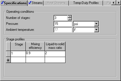
The Blocks | CCD | Input | Specifications sheet appears. Make the following specifications for a countercurrent decanter:
•Number of stages
•Operating pressure
•Mixing efficiency
•Liquid/solid ratio
If you do not provide mixing efficiency or liquid/solid ratio for all stages, Aspen Plus determines the values for missing stages by linear interpolation. If you provide only a single value for mixing efficiency or liquid/solid ratio, Aspen Plus uses that value for all stages.
By default, Aspen Plus assumes each stage of a countercurrent decanter to be adiabatic. Alternatively, you could specify a temperature, a heat duty, or a heat transfer coefficient for each stage.
1 |
Enter the following operating conditions: |
|
|
Number of stages |
3 |
|
Pressure |
15.0 psi |
2 |
For the stage profiles, enter: |
|
|
Stage |
1 |
|
Mixing efficiency |
0.9 |
|
Liquid-to-solid mass ratio |
2 |
5-18 • Modeling Polymer Recovery |
Getting Started - Solids |
3Click the Streams tab.
The CCD | Input | Streams sheet describes the connections of the streams to the stages of the CCD. It is already complete.
4Click  to continue.
The Cyclone | Input | Specifications sheet appears.
To Learn More about the Cyclone Model Using Help
Enter Specifications for the Cyclone Model
1From the main toolbar, click  .
.
2Click anywhere on the Cyclone | Input | Specifications sheet. If a small popup help window appears, click the link for Sheet Help.
The help for the Cyclone Input Specifications sheet appears.
3In the list of See Also links, click the Specifying Cyclone hypertext link.
4Use the links, scrollbars, and arrow keys to move through the topics.
5After reviewing the help, click  to close the help window.
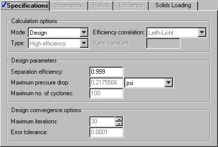
You can use the Cyclone model in simulation mode or design mode. In this simulation, use Cyclone in design mode. Aspen Plus will determine the dimensions and the number of cyclones required to achieve a specified efficiency for solids removal.
6In the Mode field, click  and select Design.
7In the Separation efficiency field, enter a separation efficiency of 0.999.
8 Click  to continue.
Getting Started - Solids |
Modeling Polymer Recovery • 5-19 |
To Specify That the Mixer Block DRIER Operates at 15 psi
Enter Specifications for the HyCyc Model
The DRIER | Input | Flash Options sheet appears. The sheet is marked complete, since there are no specifications required for a Mixer block. However, Aspen Plus does allow the pressure of the Mixer as an optional specification.
1In the Pressure field, enter 15.0 psi.
2Click  to continue.
The HCLONE | Input | Specifications sheet appears.
3From the toolbar, click  .
.
4Click anywhere on the Specifications sheet.
5Use the links, scrollbars, and arrow keys to move through the topics.
6After reviewing the help, click  to close the help window.
You can use HyCyc in simulation mode or design mode. In this example, use HyCyc in design mode. In design mode, make the following specifications:
•Particle size for design efficiency
•Design separation efficiency
•Maximum diameter of the hydrocyclone
•Maximum pressure drop
7In the Mode field, click  and select Design.
8Enter the following specifications:
Diameter of solid particles |
100 mu (microns) |
Separation efficiency |
0.95 |
Maximum diameter |
1.5 ft |
Maximum pressure drop |
5.0 psi |
Be sure to specify the units of measure for the particle diameter.
5-20 • Modeling Polymer Recovery |
Getting Started - Solids |
To help concentrate the solid slurry, change the default geometry of the hydroclone. Increasing the size of the overflow diameter increases the amount of liquid product in stream ACETONE. Specify that the ratio of the overflow diameter to the hydroclone diameter be equal to 0.3.
9Click the Dimensions tab.
10In the Diameter of overflow field, enter 0.3.
11Click  to continue.
The Required Input Complete dialog box appears.
Getting Started - Solids |
Modeling Polymer Recovery • 5-21 |