- •Contents
- •About Getting Started Modeling Processes with Solids
- •Why Use Solids Simulation?
- •Sessions in this Book
- •Using Backup Files
- •Related Documentation
- •Installation Manual
- •User Guide
- •Technical Support
- •World Wide Web
- •Hours
- •Modeling Coal Drying
- •Coal Drying Flowsheet
- •Drawing the Graphical Simulation Flowsheet
- •Stream Classes and Substreams
- •Specifying Components
- •Defining Properties
- •For More Information on the HCOALGEN Model
- •Entering Stream Data
- •Specifying Blocks
- •Using a Calculator Block to Control Drying
- •Running the Simulation
- •Examining Simulation Results
- •Exiting Aspen Plus
- •Modeling Coal Combustion
- •Coal Combustion Flowsheet
- •Starting Aspen Plus
- •Opening an Existing Run
- •If Your Saved File Solid1.apw is Not Displayed
- •Saving a Run Under a New Name
- •Drawing the Graphical Simulation Flowsheet
- •Changing the Stream Class
- •Adding Components to the Model
- •Defining Properties
- •Change the Heat of Combustion Method for Coal
- •Specify the Heat of Combustion for Coal
- •Specifying the Air Stream
- •Specifying Unit Operation Models
- •Specify the Splits for the SSplit Block
- •Defining a Calculator Block
- •Specify the Calculations to be Performed
- •Specify When the Calculator Block Should be Run
- •Running the Simulation
- •Examining Results
- •Exiting Aspen Plus
- •Modeling Gas-Solid Separators
- •Gas-Solid Separation Flowsheet
- •Starting Aspen Plus
- •Opening an Existing Run
- •If Your Saved File Solid2.apw is Not Displayed
- •Saving a Run Under a New Name
- •Drawing the Graphical Simulation Flowsheet
- •To Update the Title for This Simulation
- •Running the Simulation
- •Examining Results
- •Exiting Aspen Plus
- •Modeling Polymer Recovery
- •Polymer Recovery Flowsheet
- •Starting Aspen Plus
- •To Specify the Application Type and Run Type for the New Run
- •Drawing the Graphical Simulation Flowsheet
- •Specifying Components
- •Defining Properties
- •Defining Stream Conditions
- •Entering Block Specifications
- •Enter Specifications for the CCD Model
- •To Learn More about the Cyclone Model Using Help
- •Enter Specifications for the Cyclone Model
- •To Specify That the Mixer Block DRIER Operates at 15 psi
- •Enter Specifications for the HyCyc Model
- •Running the Simulation
- •Examining Results
- •Exiting Aspen Plus
- •Connecting to the Aspen Plus Simulation Engine
Modeling Polymer Recovery
In this simulation you will model a simplified polymer washing and drying process.
You will use:
•Component attribute GENANAL to characterize a nonconventional (NC) component
•The hydrocyclone model (HyCyc)
•The counter-current decanter model (CCD)
•The cyclone model (Cyclone)
Allow about 30 minutes to do this simulation.
Getting Started - Solids |
Modeling Polymer Recovery • 5-1 |
Polymer Recovery Flowsheet
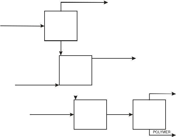
The process flow diagram and operating conditions for this simulation are shown in the following figure.
The feed stream FEED, a dilute slurry of polymer in acetone, is concentrated in a hydrocyclone. The concentrated slurry of polymer in acetone is then washed with water in a countercurrent decanter. The resulting slurry of polymer in water is dried with nitrogen. The gases from drying are separated from the solid polymer in a cyclone.
FEED
Pres = 16 psi Temp = 90 F
Acetone Flow = 1000 lb/hr Polymer Flow = 100 lb/hr
ACETONE
Eff = 0.95
for 100 microns
HCLONE
HYCYC
TO-CCD
WASH-OUT
WASH-H2O
Pres = 16 psi Temp = 200 F
H2O Flow = 400 lb/hr
CCD |
Pres = 15 psi |
|
|
|
3 stages |
CCD |
Mixing eff = 0.9 |
|
L/S ratio = 2.0 |
||
|
SLURRY |
|
|
|
|
|
|
|
HOT-N2 |
DRIER |
TO-CYCL |
|
||
Pres = 16 psi |
MIXER |
|
Temp = 350 F |
|
|
N2 Flow = 3000 lb/hr |
Pres = 15 psi |
|
|
|
VENT
CYCLONE
CYCLONE
Eff = 0.999
5-2 • Modeling Polymer Recovery |
Getting Started - Solids |