

Vlan Settings (Virtual Local Area Network)
Group individual ports into a small “Virtual” network of their own to be independent of the other ports. To add a VLAN group, press “Add Group” button, the new VLAN configuration window will pop out, you can fill in the description in order to describe this VLAN Group, check on the port to be a member to this VLAN Group, and press “Apply”button to execute the setting.

Figure 13. VLAN Group Settings
Once you want to modify the VLAN Group, check on the ID parameter, the ID VLAN configuration window will pop out.
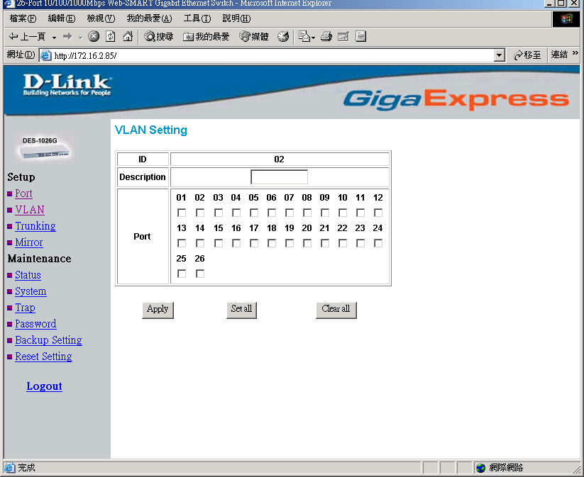
Figure 14. VLAN Settings
Trunk Setting
The Trunk function enables to cascade two devices with a double times bandwidth (up to 4000Mbps in full duplex mode).
There are two trunking groups for selection; you can select either or both groups for trunking.
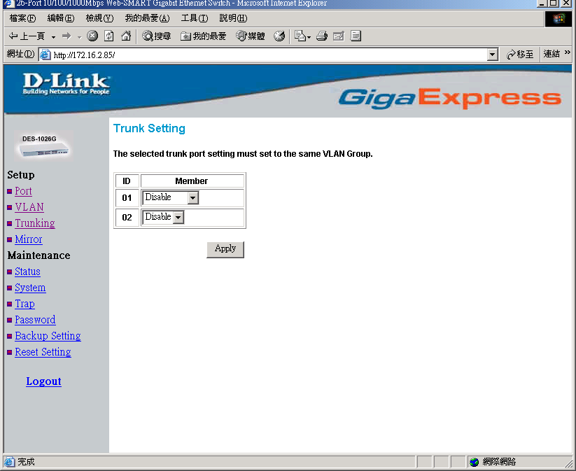
Figure 15. Trunk Settings
Be sure that the selected trunk setting port must connect to the device with a same VLAN group.
Mirror Setting
Port Mirroring is a method of monitoring network traffic that forwards a copy of each incoming and/or outgoing packetfrom oneportof a networkswitchto another port where the packet can be studied. It enables the manager to keep close track of switch performance and alter it if necessary.
Configuring the port mirroring by assigning a source port from which to copy all packets and a sniffer port where those packets will be sent.
The selection of the sniffer mode is as follow:
TX (transmit) mode:this mode will duplicate the data transmit from the source port and forward to the sniffer port.
RX (receive) mode:this mode will duplicate the data that send to the source and forward to the sniffer port.
Both (transmit and receive) mode:this mode will duplicate both the data transmit from and data that send to the source port, then it will forward to the sniffer port.
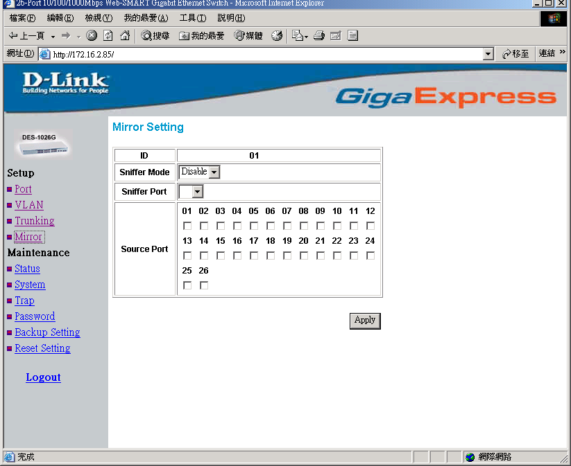
Figure 16.
Device Status
Click on the “Status”to present the device status on this screen, it will show the System Status, Port Status, VLAN Status, Trunk Status and Mirror Status..
Press “Refresh”when you need to renew the posted information.
System Setting
The System Setting includes the System name, Location name, Login Timeout, IP Address, Subnet Mask and Gateway. Through the Web Management Utility, you can easily recognize the device by using the System Name and the Location Name.
The Login Timeout is to set the idle time-out for security issue, when there is no action when running the Web Smart Utility and the time is up, you must re-login to Web Smart Utility before you set the Utility.
Fill up the IP Address, Subnet Mask and Gateway for the device.
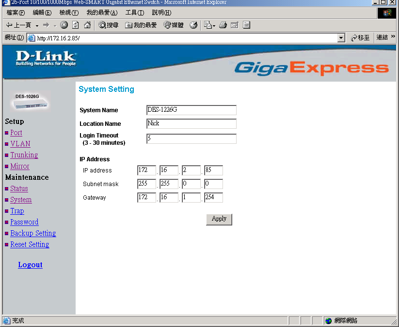
Figure 17.
Trap Setting
The Trap Setting enables the device to monitor the Trap through the Web Management Utility, set the Trap IP Address of the manager where the trap to be sent.
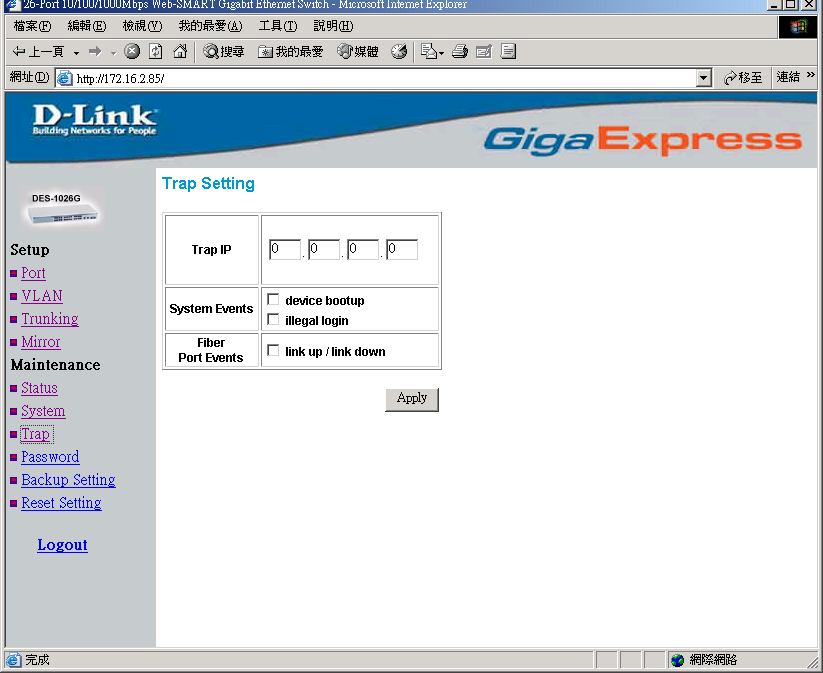
Figure 18. Trap Setting
System Events:Monitoring the system’s trap.
Device Bootup:a trap when booting up the system.
Illegal Login:a trap when there is using a wrong password login, and it will record from where the IP to be login.
Fiber Port Events:Monitoring the Fiber port status.
Link Up/Link Down:a trap when there is linking status happens in fiber port.
Copper Port Events:Monitoring the copper port status.
Abnormal* Receive Error:a trap when there are receive data error in copper port.
Abnormal* Transmit Error: a trap when there are transmit data error in copper port.
Abnormal*: 50 error packet count within 10 seconds.