

Operating Manual for R-S Rheometer
.pdfBROOKFIELD R/S RHEOMETER
Operating Instructions
Manual No. M/02-212
Brookfield Engineering Labs., Inc. |
Page 1 |
M/02-212 |
Operating Manual for R/S Rheometer
Version 1.10 E,
valid for firmware version 4.02
All rights reserved, the translation included.
Any part of this Operation Manual cannot be reproduced in any form (as printed matter, photocopies, microfilms or in any other form) or processed, copied or disseminated using electronic system without written consent of Brookfield Viscometers Ltd.
Brookfield Viscometers Ltd bears no responsibility for any technical or print technical errors or incomplete information in this Operation Manual.
We reserve the right to change this Operation Manual without previous announcement.
The reproduction of users’ names, trade names, trade marks and so on in this Operation Manual does not create the necessary prerequisites for their use by anybody; frequently it is a question of protected by law registered trade marks, even if they are not marked as such.
Copyright 1998 by
Brookfield Viscometers Ltd 1 Whitehall Estate
Flex Meadow Pinnacles West
Harlow, Essex U.K. CM19 5TJ
MS-WINDOWS - Copyright by Microsoft
IBM, IBM-PC - Registered trade marks of International Business Machines Corporation
All rights reserved
Revision |
10/9 |
Brookfield Engineering Labs., Inc. |
Page 2 |
M/02-212 |
|
|
|
CONTENTS |
|
|
I. |
GENERAL DESCRIPTION |
|
5 |
||
|
I.1 |
Use of the Rheometer |
|
5 |
|
|
I.2 |
Measuring Principle |
|
5 |
|
II. |
SYSTEM CONFIGURATION |
|
6 |
||
|
II.1 |
R/S Rheometer |
|
6 |
|
|
II.2 |
Measuring Devices |
|
8 |
|
|
II.3 |
Computer System |
|
8 |
|
III. |
INSTRUMENT INSTALLATION |
|
9 |
||
|
III.1 |
Stand Mounting |
|
9 |
|
|
III.2 |
Electrical Connections |
|
10 |
|
|
|
III.2.1 |
Temperature Sensor Pt100 |
10 |
|
|
|
III.2.2 |
AC-Adaptor |
|
11 |
|
|
III.2.3 |
Printer Connection |
|
11 |
|
|
III.2.4 |
Computer Connection |
|
11 |
|
III.3 |
Mounting of temperature controlled measuring devices |
12 |
||
|
|
III.3.1 |
Mounting of temp control device FTK-CC with and without cooling device KE 12 |
||
|
|
III.3.2 |
Mounting of the measuring device ME-CP/PP |
14 |
|
|
|
III.3.3 |
Mounting of the cooling device KE |
17 |
|
IV. ENVIRONMENT, HANDLING, CLEANING AND MAINTENANCE |
18 |
||||
|
IV.1 |
Operating environment, Storage |
|
18 |
|
|
IV.2 |
Handling |
|
18 |
|
|
IV.3 |
Cleaning |
|
18 |
|
|
IV.4 |
Maintenance |
|
19 |
|
V. MEASURING SYSTEMS |
|
20 |
|||
|
V.1 |
Measurement directly in the substance |
20 |
||
|
V.2 |
Measurement with substance in measuring system |
21 |
||
|
V.3 |
Measurement with temperature control device FTK-CC |
22 |
||
|
V.4 |
Measurement with cone/plate and plate/plate measuring systems |
23 |
||
VI. OPERATION AND MENUE SYSTEM |
25 |
||||
|
VI.1 |
Keyboard |
|
26 |
|
|
VI.2 |
Menu System of R/S Rheometer |
|
28 |
|
|
VI.3 |
Selecting from Lists |
|
29 |
|
|
VI.4 |
Input of numerical values and alphanumeric texts |
30 |
||
|
VI.5 |
Menue entries (MAIN menue) |
|
32 |
|
|
|
VI.5.1 |
MAIN-Menue → Run Single |
32 |
|
|
|
VI.5.2 |
MAIN-Menue → Run Program |
34 |
|
|
|
VI.5.3 |
MAIN menue → Remote |
|
36 |
|
|
VI.5.4 |
MAIN menue → Utilities |
|
36 |
|
|
VI.5.5 |
MAIN menue → Configuration |
36 |
|
|
VI.6 |
Menue entries in the Utilities-Menue |
37 |
||
|
|
VI.6.1Utilities → Zero Calibration |
|
37 |
|
|
|
VI.6.2 |
Utilities → Edit Programs |
|
37 |
|
|
VI.6.3 |
Utilities → Print Programs |
|
41 |
|
|
VI.6.4 |
Utilities → Measuring systems |
41 |
|
|
|
VI.6.5 |
Utilities → Print memory |
|
42 |
|
|
VI.6.6 |
Utilities → Clear memory |
|
43 |
|
|
VI.6.7 |
Utilities → Measure temperature |
43 |
|
|
|
|
|||
Brookfield Engineering Labs., Inc. |
Page 3 |
M/02-212 |
|||
|
VI.7 |
Menu entries of the CONFIGURATION menu |
44 |
|
|
|
VI.7.1 |
Configuration → Set output mode |
44 |
|
|
VI.7.2 Configuration → MeasCount mode |
45 |
|
|
|
VI.7.3 Configuration → Reset meascount |
45 |
|
|
|
VI.7.4 |
Configuration → Set Time/Date |
45 |
|
|
VI.7.5 Configuration → Set RS232 Parameter |
46 |
|
|
|
VI.7.6 |
Configuration → Language |
47 |
|
|
VI.7.7 |
Configuration → Service, Service 2 |
47 |
|
VI.8 |
Serial Data transfer via Interface RS232 |
47 |
|
VII. |
MEASUREMENTS |
50 |
||
|
VII.1 |
Measuring in manual mode |
50 |
|
|
VII.2 |
Measuring in Remote-mode |
51 |
|
VIII. TECHNICAL DATA |
52 |
|||
IX. |
GUARANTEE |
54 |
||
APPENDIX
A1 |
Data sheets of standard measuring systems |
55 |
A2 |
Error messages |
58 |
A3 |
Pin-layout of the serial data cable |
61 |
A4 |
Requirements to the mains connecting cables |
62 |
A5 |
Language cross reference |
63 |
Brookfield Engineering Labs., Inc. |
Page 4 |
M/02-212 |

I. General Description
In this chapter you get general information concerning use and measurement principle of your R/S Rheometer.
I.1 Use of the Rheometer
The R/S Rheometer system provides possibility of Newtonian fluids viscosity measurements, recording of flow curves as well as determination of viscosity functions of non-Newtonian fluids in steady shear flows. Furthermore, it assures carrying out of measurements in non-stationary shear flows and the measurements of viscoelastic substances values in creep processes. The R/S Rheometer is used in quality control, production control and researches
I.2 Measuring Principle
The R/S Rheometer is a rotational-shear rate /shear stress-rheometer.
Concentric cylinders, measuring cones and plates are available as measuring system. The measuringsample is positioned in measuring gap between the stationary measuring cup and the rotating measuring bob (Searle-principle), respectively between the rotating cone or plate and the stationary lower plate (cone/plate-, cone/cone-measuring-system).
The measuring drive developed for this instrument operates with a high dynamic precision-drive- system with optical encoder without gearing and without mechanical force transducers, so torque is measured without deflection.
The R/S Rheometer measuring drive is applicable for carrying out rotational measurements with pre-set of speed (shear rate) and pre-set of torque (shear stress).
In case of shear rate pre-set the torque acting on rotating measuring bob/cone/plate by measuring substance flow resistance is measured (shear stress is measured).
In case of shear stress pre-set resulting speed of rotating measuring bob/cone/plate is measured (shear rate).
Shear stress measurements can be carried out with R/S Rheometer in order to determine flow behavior of plastic substances and enables exact measurement of yield point without shearing the measuring substance.
The types of measurements
-rotation measurement with controlled shear rate (CSR)
-rotation measurement with controlled shear stress (CSS)
can be carried out in manual (without PC support) or in connection with a computer system with the software RHEO 2000.
The creep measurements requires computer system with software RHEO 2000.
Brookfield Engineering Labs., Inc. |
Page 5 |
M/02-212 |

II. System Configuration
In this chapter you get information concerning system configuration, temperature control device, optional computer system and dataand signal flow of your Rheometer system.
The Rheometer system R/S Rheometer consists of:
-electronic unit with measuring drive integrated in one housing
-stand with working surface
-AC-adaptor
as accessories are supplied:
•printer
•coaxial cylinder measuring system (see Appendix A)
•temperature measuring sensor Pt100
•standard measuring device ME-CP/PP for cone/plate and plate/plate measuring systems
•cone/plateand plate/plate measuring systems
•temperature control device “FTK-CC“
•cooling device “KE“
•fluids circulation thermostat
•computer system
•software RHEO 2000
bold printed accessories are necessary for minimal configuration
II.1 R/S Rheometer
The Rheometer electronics with measuring drive are built-in in one housing.
The R/S Rheometer system can serve due to consequent use of microelectronics with special capacities:
digital control of rotational speed and torque
automatic matching of control parameters during measurement
direct indication of measured and calculated values of speed, shear rate, torque, shear stress, viscosity, temperature, time etc.
internal measuring values storage
measuring values output to a printer (parallel centronics)
user support by dialog mode at LCD-display with clear text output
built-in system interface with serial standard interface (RS-232-C) for the direct connection of a computer or other serial data-loggers.
printing and serial data-transmission while measuring possible
The R/S Rheometer is operated manually using foil keyboard at the front panel or under computer control. The power supply of the R/S Rheometer with direct current is carried out by AC-adaptor.
Brookfield Engineering Labs., Inc. |
Page 6 |
M/02-212 |
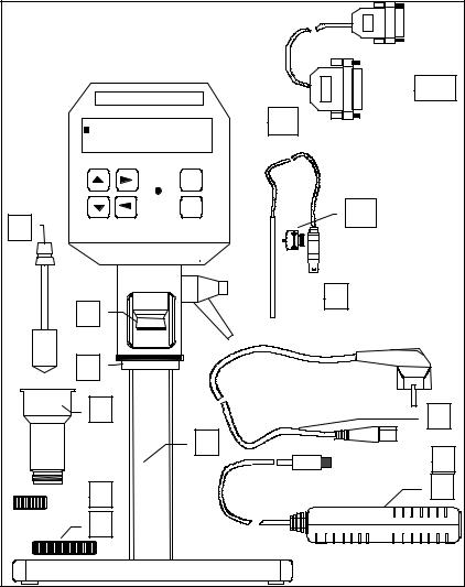
R/S Rheometer main instrument (minimum configuration)
BROOKFIELD |
|
14 |
|
|
|
Main-Menue |
|
1 |
- Run Single |
|
|
- Run Program |
|
|
- Remote |
|
|
Power |
S T |
|
|
O K |
4 |
6 |
|
|
|
|
|
2 |
|
5 |
|
|
|
3 |
|
|
7 |
|
13 |
|
|
|
|
10 |
12 |
|
|
|
8 |
|
11 |
|
|
|
9 |
|
|
1R/S Rheometer
2Measuring bob coupling
3Mounting flange
4Pt100-clamp fixture (accessory)
5Pt100 (accessory)
6Standard measuring bob (accessory)
7Standard measuring cup (accessory)
8Measuring cup bottom, or thread protection (accessory)
9Measuring cup screw fitting
10Stand
11AC-adaptor
12Direct current coupling
13Mains connection cable
14Data transmission cable (accessory
Brookfield Engineering Labs., Inc. |
Page 7 |
M/02-212 |
II.2 Measuring Devices
Measuring devices are not included in the main delivery volume of R/S Rheometer and must be ordered in accordance with your measuring requirements.
As measuring devices are optional supplied:
•coaxial standard measuring systems for R/S Rheometer (see Appendix A) with and without built-in temperature sensor Pt100
•temperature control device “FTK-CC“ for use of cylinder measuring system in temperature range -10°C ... +90°C
•cooling device “KE“ for use of cylinder measuring system in temperature range -20°C ... +180°C
•measuring device “ME-CP/PP“ for use of cone/plate or plate/plate measuring systems (see Appendix A) in temperature range -10°C ... +90°C
II.3 Computer System
The computer system is optional and provides automatic measuring, graphical representation of measuring results, printing of report as well as analysis of measuring data and quality control.
The computer system consists of:
•IBM-compatible PC with the following minimal system requirements:
-CPU 486 DX2 66 MHz
-8 MB RAM (main memory)
-10 MB free hard disk drive capacity
-operating system Microsoft Windows version 3.x, Microsoft Windows 95 or Microsoft Windows 98
-mouse and keyboard
-VGA-graphic card and monitor
-1 free serial interface RS-232
•Printer
•user software program package RHEO 2000
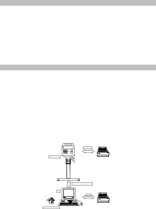
BROO KFIELD
Main-Menue
- Run Single
- Run Program
- Remote
Power S T
O K
R/S Rheom eter
Centronics
Printer when using R/S Rheom eter without Com puter
PC
Software RHEO 2000
RS232 (Data transm ission)
Printer when using R/S Rheom eter rem ote controlled
LPT1
Fig. 1.: Computer system for R/S Rheometer
Brookfield Engineering Labs., Inc. |
Page 8 |
M/02-212 |
III. Instrument Installation
In this chapter you will know how to prepare your R/S Rheometer for the first measurements.
You will know particularly,
-how to mount the R/S Rheometer,
-details about the electric connections
-installation of accessories such as temperature control device, cooling device, measuring system
-hose connections.
III.1 Stand Mounting
The stand consists of:
-the stand base plate
-the stand column with Rheometer
-the shelf
Hex-nut wrench size 6 and bolt DIN 912 M8x40 are supplied for mounting.
1.The stand column is joined with the stand base plate by the supplied bolt. It is necessary to check during this operation that the parallel pin at the down side of the stand column fits into the corresponding drilled hole at the base plate.
2.Lay the shelf on the stand base plate.
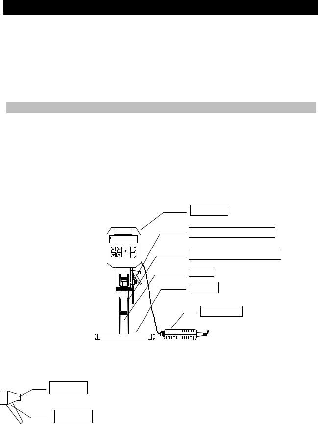
Rheometer
Brookfield
Pt100-temperature-sensor
Main-Menue
-Run Single
-Run Program
-Remote
Power |
S T |
|
O K |
Cylindric measuring system
Stand
Shelf
AC-adaptor
Fig. 2.: R/S Rheometer (minimum configuration)
Hints for height adjustment of the stand:
Locking button
Clamp handle
In order to change the height adjustment of the stand you must release the clamp handle and move the stand to the desired height. Caution:
Hold tight the R/S Rheometer as you release the clamp handle!
You can press the locking button to change the clamp handle position without screw/unscrew the thread.
After adjustment of the height screw tight the clamp handle thread again with hand
Brookfield Engineering Labs., Inc. |
Page 9 |
M/02-212 |
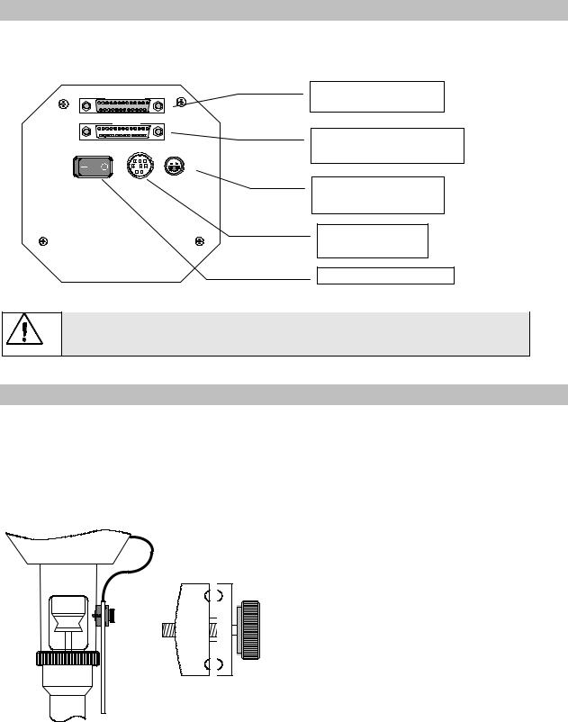
III.2 Electrical Connections
Connections for the electrical components of the R/S Rheometer are located at the instrument back side:
Centronics
RS232 |
|
Power |
|
|
DC |
|
Pt 100 |
|
|
|
|
|
|
|
|
|
|
|
|
|
|
|
|
|
|
|
|
|
|
|
|
|
|
|
|
|
Socket “Centronics“ parallel Printer interface
Socket “RS232“
serial communication port
Socket “Pt100“
for temperature sensor
Socket “DC“ for ACadaptor connection
Mains switch “POWER“
Any cables from and to R/S Rheometer can be connected or disconnected only when instrument is switched off!
III.2.1 Temperature Sensor Pt100
The connecting cable of the temperature sensor Pt100 is inserted into connector “Pt100“ at the back side of the R/S Rheometer.
The Pt100 used is dependent upon measuring system device.
If you use standard cylindric measuring cups (MB-CC45...CC8) for measurements, put the sensor Pt100 into Pt100 clamp fixture and fix it parallel to the measuring system at mounting flange of the R/S Rheometer with the help of knurled-head screw.
Fig. 3: Pt100 connection and mounting
Insert the plug of Pt100 temperature sensor into the connector “Pt100” at the back side of the Rheometer.
As the viscosity is a function of the temperature, the temperature should be measured preferly in the measuring substance. For this purpose, the standard measuring systems CC45...CC8 DIN can be equipped with a Pt100 in measuring cup bottom (only in connection with FTK-CC). If you use a measuring system with built-in Pt100, insert the cable “VK-MB“ there. With this option you can measure the substance temperature directly.
Brookfield Engineering Labs., Inc. |
Page 10 |
M/02-212 |