

8J - 6 TURN SIGNALS AND HAZARD WARNING FLASHER |
|
Ä |
|
Fig. 9 Remote Turn Signal SwitchÐAG and AJ Bod-
ies
(5)For installation reverse above procedure.
(6)Check for proper operation of all components which are controlled by the pod mounted switch.
TURN SIGNAL AND HAZARD WARNING FLASHER LOCATION
AA, AC, AP AND AY BODIES
The turn signal flasher and the hazard warning flasher are two separate plug-in type units.
On AC and AY both flashers are on the relay module (Fig. 10).
Fig. 10 Turn Signal and Hazard Warning
FlasherÐAC and AY Bodies
On AA and AP Bodies the hazard flasher is located on the relay module (Fig. 11). The turn signal flasher is on the driver's side of A/C duct for AA Body (Fig. 12) and center A/C duct for AP Body.
AG AND AJ BODIES
The turn signal flasher and the hazard warning flasher are combined into one unit called a combination flasher (combo-flasher). The combo-flasher controls the flashing of the hazard warning system and
Fig. 11 Hazard Warning FlasherÐAA and AP Bodies
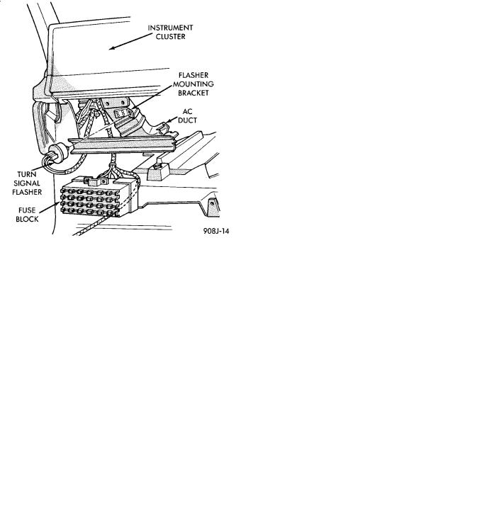
Fig. 12 Turn Signal FlasherÐAA Body
the turn signal system. An inoperative bulb or incomplete turn signal circuit will result in an increase in flasher speed.
The combo-flasher is located under the instrument panel, right of the steering column and is clipped on the A/C distribution duct. The combo-flasher is yellow in color for ease of identification.
TURN SIGNAL RELAYSÐAG AND AJ BODIES
The AG and AJ models are equipped with four turn signal relays.
Ä |
|
TURN SIGNALS AND HAZARD WARNING FLASHER 8J - 7 |
|
² One relay controls the right rear turn signal and stop lamp. The second relay controls the left rear turn signal and stop lamp. The third relay controls the right front turn signal. The fourth relay controls the left front turn signal.
The turn signal relays are located in the relay bank, underneath the driver's side of the instrument panel. The four turn signal relays are identical and can be interchanged.
The turn signal relays do not cycle on and off with the turn signal lamp. Their function is to complete
the turn signal circuit when the turn signal is switched on. Turn signal cycling is done by the combination flasher.
To test the relay, remove the suspect relay and switch it with 1 of the other 3 turn signal relays. If the problem follows the relay, replace that relay. If the problem remains in the same circuit, the relay is not the problem. Refer to Group 8W, Wiring Diagrams.