- •CONTENTS
- •GENERAL INFORMATION
- •DOOR LOCK INHIBIT
- •KEYLESS ENTRY SYSTEM
- •CIRCUIT BREAKER TEST
- •WIRING VOLTAGE TEST
- •SWITCH TEST
- •ELECTRIC MOTOR TEST
- •POWER DOOR LOCKS
- •DOOR LOCK SYSTEM TEST
- •DOOR LOCK MOTOR REPLACEMENT
- •DECK LID OPERATION
- •TEST
- •ADJUSTMENT
- •POWER PULL DOWN
- •REMOTE KEYLESS ENTRY
- •OPERATION
- •CONTROL RANGE
- •TRANSMITTER BATTERY
- •PROGRAM REMOTE KEYLESS ENTRY
- •HORN CHIRP CANCELLATION
- •TESTING
- •REMOTE KEYLESS MODULE REPLACEMENT
- •LAMP OUTAGE MODULE REPLACEMENT
- •DOOR LOCK INHIBIT
- •AC, AG, AJ AND AY BODIES
- •AA BODY
Ä |
|
POWER LOCKS 8P - 1 |
|
POWER LOCKS
CONTENTS
|
page |
CIRCUIT BREAKER TEST . . . . . . . . . . . . . . . . |
. . 1 |
DECK LID OPERATION . . . . . . . . . . . . . . . . . . |
. . 4 |
DECK LID PULL-DOWN SYSTEM ± AC and AY |
|
BODIES . . . . . . . . . . . . . . . . . . . . . . . . . . . . |
. . 4 |
DOOR LOCK INHIBIT . . . . . . . . . . . . . . . . . . . |
. . 8 |
DOOR LOCK INHIBIT . . . . . . . . . . . . . . . . . . . |
. . 1 |
DOOR LOCK MOTOR REPLACEMENT . . . . . . |
. . 3 |
DOOR LOCK SYSTEM TEST . . . . . . . . . . . . . . |
. . 3 |
ELECTRIC MOTOR TEST . . . . . . . . . . . . . . . . . |
. . 2 |
GENERAL INFORMATION
All doors can be locked or unlocked electrically by operating the switch on a front door panel or arm rest.
The rear doors can be locked or unlocked by actuation of the front door switch, or can be locked or unlocked mechanically and independently with their respective locking knobs.
The front doors can be locked or unlocked mechanically with the locking knob regardless of electrical locking and unlocking actuation with the front door knobs.
The right and left front door on all car lines can be locked or unlocked mechanically from the outside with the key or electrically as described above. The left front can also be unlocked by actuation of the inside remote door handle. The right front door on AC, AG, AJ and AY can be unlocked by actuation of the inside remote door handle.
The deck lid lock consists of a latch with internal solenoid and push button switch. The solenoid is energized only when the push button is depressed.
DOOR LOCK INHIBIT
The power door lock inhibit system prevents the doors from being locked using the power door locks when either of two conditions occur:
(1)The key is in the ignition switch and any of the doors are open. The ignition switch does not have to be ON.
(2)The key is in the ignition switch and the headlamps are on.
KEYLESS ENTRY SYSTEM
The system allows locking and unlocking of vehicle door(s) and Trunk lid by remote control using a hand held radio transmitter. The ignition switch must be OFF before the trunk lid can be unlocked with the transmitter.
|
page |
GENERAL INFORMATION . . . . . . . . . . . . . . . . |
. . 1 |
KEYLESS ENTRY SYSTEM . . . . . . . . . . . . . . . |
. . 1 |
LAMP OUTAGE MODULE REPLACEMENT . . . . . 8 |
|
POWER DOOR LOCKS . . . . . . . . . . . . . . . . . . |
. . 2 |
POWER PULL DOWN . . . . . . . . . . . . . . . . . . . |
. . 4 |
REMOTE KEYLESS ENTRY . . . . . . . . . . . . . . . |
. . 5 |
REMOTE KEYLESS MODULE REPLACEMENT |
. . 8 |
SWITCH TEST . . . . . . . . . . . . . . . . . . . . . . . . . |
. . 1 |
WIRING VOLTAGE TEST . . . . . . . . . . . . . . . . . |
. . 1 |
The receiver may receive signals from two transmitters. Each transmitter has its own code, and the code has been stored in memory. If the transmitter is replaced or a second transmitter is added, the code on both units have to be placed in memory.
CIRCUIT BREAKER TEST
Find correct circuit breaker on fuse block. Pull out slightly but be sure that circuit breaker terminals still contact terminals in fuse block. Connect ground wire of voltmeter to a good ground. With probe of voltmeter positive wire, check both terminals of circuit breaker for 12 volts. If only one terminal checks at 12 volts, circuit breaker is defective and must be replaced. If neither terminal shows 12 volts, check for open or shorted circuit to circuit breaker.
WIRING VOLTAGE TEST
The following wiring test sequence determines whether or not voltage is continuous through the body harness to switch.
(1)Remove left side switch from trim panel.
(2)Carefully separate multiple terminal block on wiring harness from switch body.
(3)Connect one lead of test light to a ground termi-
nal:
²Black Wire AA and AC Bodies
²Gray wire AG and AJ Bodies
²Touch other test light lead to Red Wire terminal.
²If test light comes on, the wiring circuit between the battery and switch is functional.
²If test light does not come on, check 30 amp circuit breaker or for a open circuit.
SWITCH TEST
Remove the switch from its mounting location. Using an ohmmeter, refer to (Fig. 1) to determine if

8P - 2 POWER LOCKS |
|
Ä |
|
continuity is correct in the Lock and Unlock switch positions. If these results are not obtained, replace the switch.
Fig. 1 Door Lock Switch Continuity
ELECTRIC MOTOR TEST
Make certain battery is in normal charged condition before circuits are tested.
To determine which motor is faulty, check each individual door for electrical lock and unlock or disconnect the motor connectors one at a time, while operating the door lock switch. In the event that none of the motors work, the problem may be caused by a shorted motor, or a bad switch. Disconnecting the defective motor will allow the others to work.
The power lock motors are also equipped with a thermal protection system which prevents the motors from burning out. The motors may chatter if they are continuously activated.
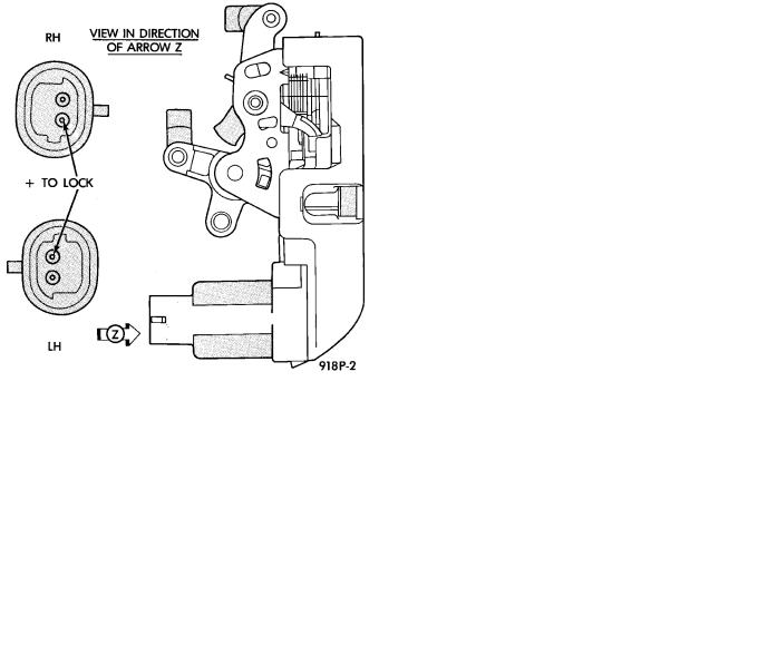
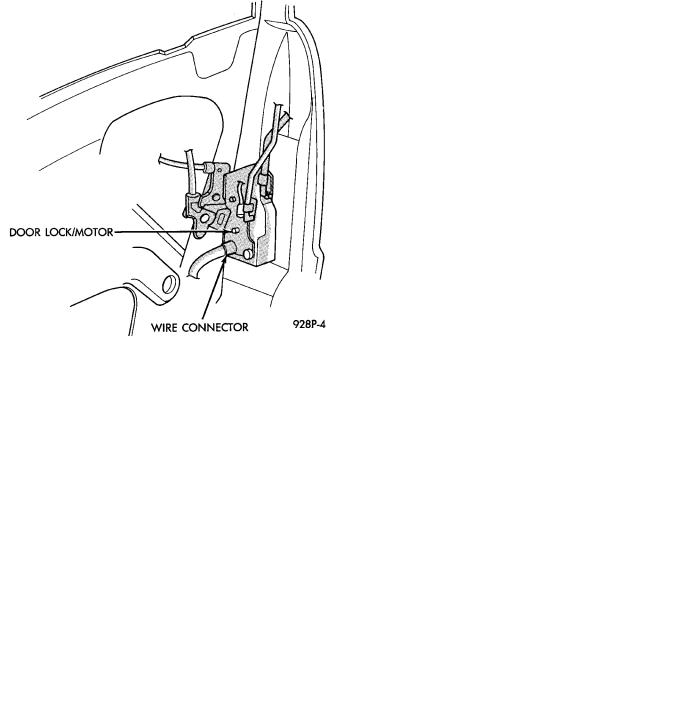
To test an individual door lock motor, disconnect the wire connector at the motor (Fig. 2 and 3). Test at the connector for 12 volts while applying the door lock switch. If no voltage repair wire. Apply 12 volts to the motor terminal, and a known good ground to the other terminal to check motor operation.
Should the motor defect be a result of a broken wire, it should have no effect on the operation of the other motors.
POWER DOOR LOCKS
When AC, AG, AJ or AY Body vehicles are equipped with power door locks, the system includes an automatic door locking feature which is actuated through the vehicle's body controller.
Fig. 2 Door Lock Motor
Fig. 3 Door Latch with Lock Motor ± AC and AY Bodies
When this system is enabled the automatic door locks will work automatically. When the system is disabled the door locks will work by use of the door lock switches only.
The body controller controls the power locks when the door lock switch is activated. If the door lock switch is pressed for longer than eight consecutive seconds, the body controller will de-energize the door lock relay. Also, the body controller will automatically lock all doors when all of the conditions below are met:
²All doors are closed
²The vehicle speed exceeds 15 ± 1 MPH
²The throttle position sensor tip-in is greater than 10 ± 2 degrees.

Ä |
|
POWER LOCKS 8P - 3 |
|
The DRB II must be used to enable/disable the automatic door lock system. Refer to the Body Diagnostic Procedures Manual for the procedure.
The body controller will automatically re-lock all doors if the above conditions are met and if any of the door become ajar. The body controller does not control the door unlock function. The switch is wired directly to the lock relay.
DOOR LOCK SYSTEM TEST
For complete testing of the AC, AG, AJ and AY body automatic door lock systems, refer to the Body Diagnostic Procedures Manual.
DOOR LOCK MOTOR REPLACEMENT
(1)Remove inside door release handle, window regulator handle, if equipped and door trim panel.
(2)Roll door watershield away from lower rear corner of door to reveal inside panel access opening.
(3)Disconnect link at the motor as required (Fig. 4 through 7).
Fig. 4 Front Power Door Lock Motors ± AA, AG, AJ
and AP Bodies
(4)Disconnect motor lead wires.
(5)Remove motor or latch attaching screws and remove motor assembly.
(6)For installation reverse above procedures.
Fig. 5 Rear Power Door Lock Motors ± AA and AP
Bodies
Fig. 6 Front Power Door Lock Motors ± AC and AY
Bodies
